BL57-NE
3-12
(E)
5
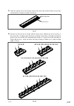
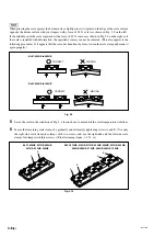
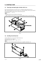
Remove the stopper from the detector head.
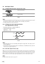
Fig. 3-16
6
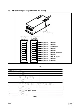
Move the scale, and make sure that the amplitudes A and B (see Fig. 3-17) of the Lissajous’ figure are
within the range of the specified values over the entire length.
<Specified values>
A/B signal output type ..... Output format A : Amplitude 0.9 Vp-p to 1.8 Vp-p
Output format F : Amplitude 0.7 Vp-p to 1.3 Vp-p
Output format G : Amplitude 0.8 Vp-p to 1.2 Vp-p
Analog output type ........... Output format H : Amplitude 0.6 Vp-p to 1.1 Vp-p
For output format A, the center of the Lissajous’ figure is 0 V. For output format F, G, and H, the center
of the Lissajous’ figure is 2.5 V.
If the output of 1 Vp-p cannot be obtained even through repeated adjustment, recheck the mounting
surface accuracy of the scale and detector head (refer to pages 3-3 to 3-4), and check again that there is
no dirt on the scale’s surface.
Fig. 3-17
Lissajous
B
A
Stopper
Do not move the machine device with
the stopper attached to detector
head because this may result in
breakage of the detector head or the
scale.
Summary of Contents for BL57-003NE Series
Page 2: ...BL57 NE...
Page 8: ...6 E BL57 NE...
Page 10: ...ii E BL57 NE...
Page 14: ...2 2 E BL57 NE...
Page 28: ...BL57 NE 3 14 E...
Page 36: ...4 8 E BL57 NE...
Page 48: ...7 4 E BL57 NE...
Page 50: ...8 2 E BL57 NE...
Page 58: ...ii G BL57 NE...
Page 62: ...2 2 G BL57 NE...
Page 76: ...BL57 NE 3 14 G...
Page 84: ...4 8 G BL57 NE...
Page 96: ...7 4 G BL57 NE...
Page 98: ...8 2 G BL57 NE...

