4-4
(E)
BL57-NE
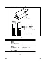
4-4-1. Detailed Description of MODE Switches
MODE switches 1, 2, 4, 7, 9 and 10
These switches are not used. Always use in the OFF setting.
MODE switch 3 (Direction switch)
This switch is used to change the positional relationship between scale movement direction and A/B signal.
For more information, see section 4-5-1, “Changing the Direction.”
MODE switch 5
This switch is not used. Always use in the ON setting.
MODE switch 6 (Resolution setting switch)
This switch is used to set the resolution. For output form F types, setting this switch to ON sets 0.1
µ
m and
setting to OFF sets 0.05
µ
m. For G types, setting to ON sets 0.02
µ
m and setting to OFF sets 0.01
µ
m.
MODE switch 8 (Alarm mode switch)
This switch is used to select the alarm output format.
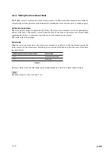
For more information, see section 4-5-3, “Setting the Alarm Reset Mode.”
4-5. Changing the Settings (For output format F, and G only)
4-5-1. Changing the Direction
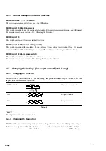
MODE switch 3 (Direction switch) is used to change the positional relationship of the A/B signal with
respect to the scale movement direction.
MODE switch 3
Moves to head cable side
OFF
A signal is leading
ON
B signal is leading
Table 4-2
For output format A, refer to section 4-6-1.
4-5-2. Changing the Resolution
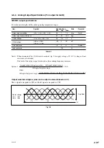
MODE switch 6 (resolution setting switch) is used to change the resolution of the A/B signal output type.
In the case of output format F: ON = 0.1
µ
m
In the case of output format G: ON = 0.02
µ
m
OFF = 0.05
µ
m
OFF = 0.01
µ
m
A
B
A
B
Summary of Contents for BL57-003NE Series
Page 2: ...BL57 NE...
Page 8: ...6 E BL57 NE...
Page 10: ...ii E BL57 NE...
Page 14: ...2 2 E BL57 NE...
Page 28: ...BL57 NE 3 14 E...
Page 36: ...4 8 E BL57 NE...
Page 48: ...7 4 E BL57 NE...
Page 50: ...8 2 E BL57 NE...
Page 58: ...ii G BL57 NE...
Page 62: ...2 2 G BL57 NE...
Page 76: ...BL57 NE 3 14 G...
Page 84: ...4 8 G BL57 NE...
Page 96: ...7 4 G BL57 NE...
Page 98: ...8 2 G BL57 NE...

