BL57-NE
(E)
4-7
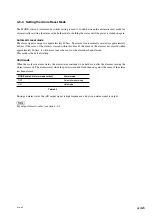
Center voltage
+
V
OA
+
V
OB
−
V
OA
−
V
OB
−
V
A
+
V
A
0 V
+
V
B
−
V
B
Amplitude
4-6-4. Analog Output Specifications (For output format H)
SIN/COS output specifications
(Over the entire length and the entire operating temperature range)
Item
Symbol
Specifications
Units
Remarks
Min.
Typ.
Max.
Output signal amplitude
(+V
A
)
−
(
−
V
A
), (
+
V
B
)
−
(
−
V
B
)
0.6
1
1.2
Vp-p
Note 1
Output signal phase difference
80
90
100
deg
Center voltage
+
V
OA
,
+
V
OB
,
−
V
OA
,
−
V
OB
2.3
2.5
2.7
V
Offset voltage
(
+
V
OA
)
−
(
−
V
OA
),
−
50
0
50
mV
(+V
OB
)
−
(
−
V
OB
)
Gain unbalance
−
6
0
6
%
System 1
Load resistance
120
Ω
Table 4-5
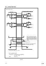
Note 1: When terminator Z0 = 120
Ω
(refer to section 5, fig. 5-6) supply voltage = 5 V
±
5 % (voltage of load
resistance at both ends)
The level of the output signal is reduced as the scanning frequency increases.
System 1:
A signal output voltage p-p value
−
AB signal output average
×
100
AB signal output average
where
AB signal output average =
A signal output voltage p-p value + B signal output voltage p-p value
2
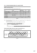
Output waveform diagram (when each output is viewed based on 0 V)
The A signal corresponds to SIN, and the B signal corresponds to COS.
Fig. 4-6
Summary of Contents for BL57-003NE Series
Page 2: ...BL57 NE...
Page 8: ...6 E BL57 NE...
Page 10: ...ii E BL57 NE...
Page 14: ...2 2 E BL57 NE...
Page 28: ...BL57 NE 3 14 E...
Page 36: ...4 8 E BL57 NE...
Page 48: ...7 4 E BL57 NE...
Page 50: ...8 2 E BL57 NE...
Page 58: ...ii G BL57 NE...
Page 62: ...2 2 G BL57 NE...
Page 76: ...BL57 NE 3 14 G...
Page 84: ...4 8 G BL57 NE...
Page 96: ...7 4 G BL57 NE...
Page 98: ...8 2 G BL57 NE...

