BL57-NE
(E)
5-5
A
+
SIN
B
U0
U0
+
5 V
+
5 V S
0 V S
+
5 V
+
COS
−
SIN
−
COS
GND
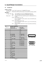
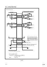
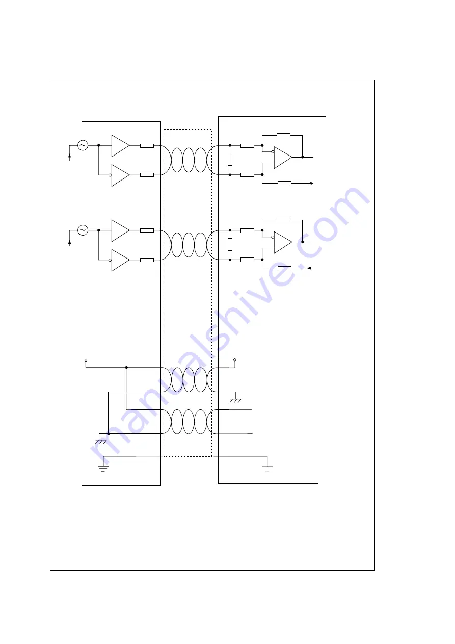
Sensor circuit
Reference example of receive side
Scale side
Connect to
+
5 V and GND if there is
no remote sensing function.
GND
FG
FG
Aa
U1
Ba
U1
Z0
R1
R1
R2
R2
Z0
R1
R1
R2
R2
When receiving power from sources
other than the controller, connect the
controller's power supply ground to
the power supply ground of the power
supply unit to place them at the same
potential.
51
Ω
51
Ω
51
Ω
51
Ω
U0 = U1 = 2.5 V
±
0.2 V
Z0 = 120
Ω
Recommended elements
SIN and COS : Differential receiver LMH6654
R1 = R2 = 10 k
Ω
REF
: DS34C86
Example of input circuit
5-2-2. Analog Output Type
Fig. 5-6
Summary of Contents for BL57-003NE Series
Page 2: ...BL57 NE...
Page 8: ...6 E BL57 NE...
Page 10: ...ii E BL57 NE...
Page 14: ...2 2 E BL57 NE...
Page 28: ...BL57 NE 3 14 E...
Page 36: ...4 8 E BL57 NE...
Page 48: ...7 4 E BL57 NE...
Page 50: ...8 2 E BL57 NE...
Page 58: ...ii G BL57 NE...
Page 62: ...2 2 G BL57 NE...
Page 76: ...BL57 NE 3 14 G...
Page 84: ...4 8 G BL57 NE...
Page 96: ...7 4 G BL57 NE...
Page 98: ...8 2 G BL57 NE...

