BL57-RE
(E)
3-1
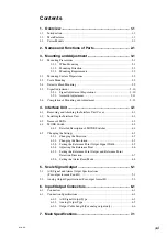
3. Mounting and Adjustment
Follow the procedure below. (For details refer to the corresponding pages.)
3-1. Mounting Precautions ....................................................................................................................... 3-1
3-1-1. When Mounting .................................................................................................................... 3-1
3-1-2. Mounting Direction ............................................................................................................... 3-2
3-1-3. Mounting Requirements ........................................................................................................ 3-2
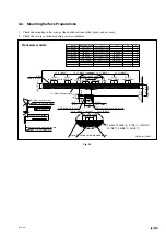
3-2. Mounting Surface Preparations ........................................................................................................ 3-3
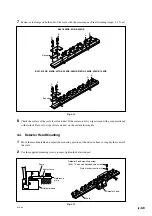
3-3. Scale Mounting ................................................................................................................................. 3-5
3-4. Detector Head Mounting .................................................................................................................. 3-9
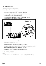
3-5. Signal Adjustment .......................................................................................................................... 3-10
3-5-1. Signal Adjustment Preparations .......................................................................................... 3-10
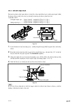
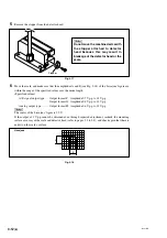
3-5-2. Azimuth Adjustment ........................................................................................................... 3-11
3-6. Completion of Mounting and Adjustment ...................................................................................... 3-13
3-1. Mounting Precautions
3-1-1. When Mounting
•
The scale and the detector head are adjusted to each other. If using more than one scale unit, be sure that
the scale-head combinations have matching serial numbers.
•
Consider the mounting position (Abbe error) and the environmental conditions (temperature, humidity,
vibration and dust) thoroughly.
•
Do not lead the head cable through the same duct with the power cable. Also, do not bundle the head cable
and power cable together using a tie.
•
Install in a location that is at least 0.5 meters separated from sources of high voltage and large currents
and large power relays.
•
Do not use the cable connecting the detector head to the interface unit in a location where it is likely to be
repeatedly subjected to a bending force (cable bear, etc.). In such a case, bend the cable connected to the
output connector on the interface unit.
•
Use this product in an environment with an ambient temperature of 0 to 40
°
C.
Do not attach it to a location that is exposed to direct sunlight or warm air or near sources of heat such as
motors. This could adversely affect the accuracy.
•
If using a water-soluble cutting fluid or other substances, ensure that there is adequate protection so that
it does not adhere to the scale.
•
Set the maximum travel of the machine’s moving part shorter than that of the scale.
Scale’s max. travel = measuring 10 mm/0.39" (5 mm/0.20" per each side)
(If the scale’s max. travel is exceeded, the scale unit signals will not be output and an error will occur.)
•
For the scale unit, scale signal adjustment is necessary after mounting. When mounting the scale to the
machine, make sure that there is enough space for the adjustment. (See pages 3-3 to 3-13.)
•
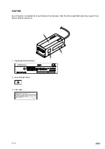
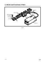
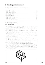
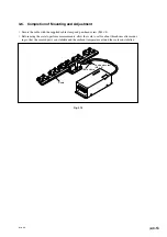
When mounting and adjusting the detector head, do not touch the surface of the head cover indicated by
the arrows in the drawing below.
Fig. 3-1
Summary of Contents for BL57-RE
Page 2: ...BL57 RE...
Page 8: ...6 E BL57 RE...
Page 14: ...2 2 E BL57 RE...
Page 28: ...BL57 RE 3 14 E...
Page 40: ...5 4 E BL57 RE...
Page 52: ...8 4 E BL57 RE...
Page 54: ...9 2 E BL57 RE...
Page 66: ...2 2 G BL57 RE...
Page 80: ...BL57 RE 3 14 G...
Page 92: ...5 4 G BL57 RE...
Page 104: ...8 4 G BL57 RE...
Page 106: ...9 2 G BL57 RE...


