BL57-RE
(E)
4-7
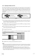
ON
OFF
ON
OFF
4-5-5. Setting the Reference Point Output and Reference Point Detection
Direction
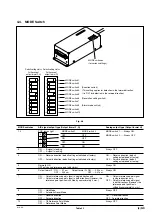
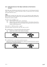
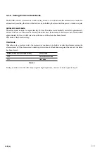
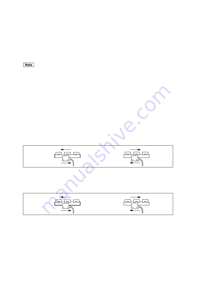
The MODE switch 7 (Reference point output selector switch) is used to set the reference point output to
output in a single direction or output in both directions. When set to single direction (ON), the reference
point detection direction can be set.
If MODE switch 7 (Reference point output selector switch) is set to both directions (OFF), MODE switch 4
(Default reference point detection direction setting switch) and MODE switch 9 (Reference point detection
direction selector switch) are disabled.
1
Make the setting for MODE switch 7.
ON ......... Outputs the reference point signal in a single direction
OFF ....... Outputs reference point signal in both directions (However, the reference point position is
shifted by approximately 4 mm when detecting in the opposite direction from the default
reference point detection direction.)
If the switch is set to OFF, the procedure is completed.
Perform the procedure starting from step 2 only if the switch is set to ON.
2
Use MODE switch 4 to set the default reference point detection direction.
ON ......... Default reference point detection is in the reverse direction
OFF ....... Default reference point detection is in the forward direction
3
Use MODE switch 9 to set the reference point detection direction.
In this case, the reference point detection position is not shifted even if the detection direction is opposite
the default reference point detection direction.
Summary of Contents for BL57-RE
Page 2: ...BL57 RE...
Page 8: ...6 E BL57 RE...
Page 14: ...2 2 E BL57 RE...
Page 28: ...BL57 RE 3 14 E...
Page 40: ...5 4 E BL57 RE...
Page 52: ...8 4 E BL57 RE...
Page 54: ...9 2 E BL57 RE...
Page 66: ...2 2 G BL57 RE...
Page 80: ...BL57 RE 3 14 G...
Page 92: ...5 4 G BL57 RE...
Page 104: ...8 4 G BL57 RE...
Page 106: ...9 2 G BL57 RE...

