15
Level surface set up
▪
Select a place as close and practical to
the work site as possible, and ensure that
the location is clear of traffic.
▪
Place the laser level onto a reasonably
level surface with the control panel facing
upwards.
Tripod set up
▪
Select a place as close and practical to
the work site as possible, and ensure that
the location is clear of traffic.
▪
Extend the tripod legs to the required
height and then spread the legs wide
enough so that the tripod platform is
stable.
▪
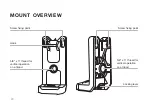
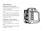
Connect the mount to the back of the
laser (see page 18-19).
▪
Place the instrument onto the tripod
with the control panel facing upwards
and thread the yoke into the mount on the
back of the instrument until firm. Do not
over tighten as this may cause damage to
the instrument or tripod.
VERTICAL MEASUREMENT SET UP
Summary of Contents for HV2G
Page 1: ...H V 2 G R O TA R Y L A S E R I N S T R U C T I O N M A N U A L...
Page 5: ...5 Rotating laser port Charging port Control panel LASER OVERVIEW FRONT Battery screw...
Page 9: ...9 REMOTE CONTROL OVERVIEW BACK Battery compartment...
Page 11: ...11 DETECTOR OVERVIEW BACK Battery compartment Staff clamp thread LCD display screen...
Page 28: ...www spoton com au...


