
USER MANUAL: Laserworld CS-200RGY
Date: 01/2008
Page 8 of 11
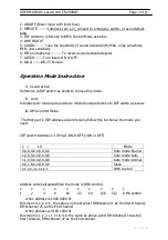
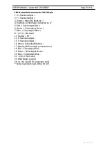
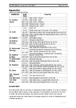
DMX Channel Instruction----------12CHS single/three color
Please refer to appendix1
D.
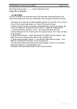
ILDA Mode
This laser projector has designed with a ILDA automatic switching feature.ILDA
mode will be active when the pin-25 female(on the rear panel) was be connected.
All outputs are located at an ILDA-standard connector (In and Out). This can be a
25-pin D-Sub connector(female) or a 25-pin IDC-connector(male).
The IDC-connector allows to connect a separate D-Sub connector by using a flat
cable. All outputs are symmetrical and be used in 3 different configurations:
1. symmetrical signal. O and – are connected directly with the
corresponding pins of the receiving unit. For signal inversion, the 2 lines just have
to be crossed.
2. Single ended. Output – will be grounded to 0V (GND) and the o and
GND have to be connectd to the inputs of the receiving unit.
3. Single ended inverted. is grounded to GND and the outputs – and
GND are connected to the inputs of the receiving unit.
The maximum signal level between the scanneroutputs X and Y is 10V and the
signal level between, the coloroutputs is 5V.
All outputs can be grounded and are short circuit protected.