
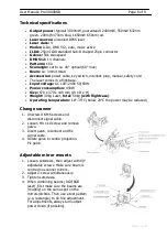
User Manual: Pro-3000RGB
Stand: 11/2008
Page 7 of 9
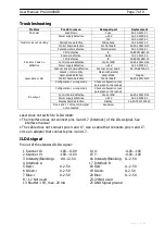
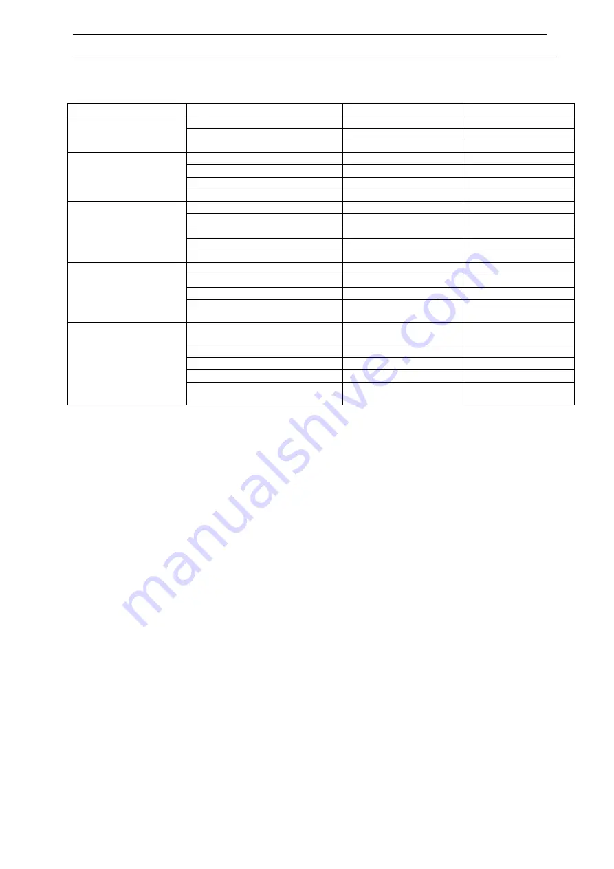
Troubleshooting
Problem
Possible reason
Damaged part
Replacement
Fuse blown
Fuse
09-00-3001-01
+-24V
16-03-0039-00
No power
Power supply defective
12V
19-03-0019-00
Microphone defective
Microphone
16-03-0001-00
Control board defective
Control board
26-2A-2009LD-00
Potentiometer defective
Potentiometer
04-03-0104-01
Music mode not working
CPU defective
IC
00-89C516ED-00
Scanner defective
Galvo
15-01-2215-00
CPU defective
IC
00-89C516ED-00
Control board defective
Control PCB
26-2A-2009LD-00
Power supply defective
+-24V
16-03-0039-00
X and/or Y axis no
deflection
Scanner driver board defective
Scanner driver board
26-2A-6800A-00
Lenses / mirrors dirty
Clean with alcohol
Laser diode defective
Laser diode
Inquire
Control board defective
Control board
26-2A-2009LD-00
Laser dark or dim
Configuration / wrong mode
Check configuration (see
paragraph control panel)
Configuration / wrong mode
Check configuration (see
paragraph control panel)
Control board defective
Control PCB
26-2A-2009LD-00
Power supply defective
+-24V
16-03-0039-00
Display board defective
Display
26-2A-YX2012DI-00
No output
Pins 4 and 17 of the ILDA signal
not connected
See below
Laser does not switch to ILDA mode:
•
The interface does not connect pins 4 and 17 (Interlock) of the IDLA signal. See
interface manual
•
The cable does not connect pins 4 and 17. Use a cable that connects pins 4 and 17.
•
Use an adapter that connects pins 4 and 17.
ILDA signal
Pin out of the standard ILDA signal:
1 Scanner X+
-10V..+10V
14 X-
+10V..-10V
2 Scanner Y+
-10V..+10V
15 Y-
+10V..-10V
3 Intensity/B
0V..+2.5V
16 Intensity/Blanking- 0..-2.5V
4 Interlock A
17 Interlock B
5 Red+
0..2.5V
18 Red-
0..-2.5V
6 Green+
0..2.5V
19 Green-
0..2.5V
7 Blue+
0..2.5V
20 Blue-
0..-2.5V
8 – 12 Not used
23-24 Not used
13 S5V, max. 20 mA
25 GND Signal ground


