6.3 Wiring system of entry phone in video version
6 INSTALLATION AND ACTIVATION
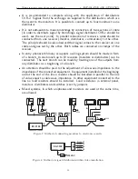
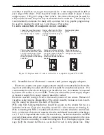
Connection between electronic cassette and uniphones should be made by
means of any double wire e.g. YTDY. In case of gate control min. 4 wire
conductor should be used.
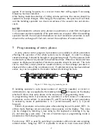
In audio version the routing of wiring system from electronic cassette to uni-
phones does not make any difference. Each uniphone can be connected by
a separate wire, wiring can be router from one uniphone to the next one or
uniphones can be connected on a common bus-bar. The distance between
a uniphone and an electronic cassette should not exceed 150m.
EC-3100
230 VAC
4
Power supply
2
2
2
2 2
2 2
Figure 6: Method of connecting uniphones to electronic cassette.
6.3
Wiring system of entry phone in video version
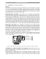
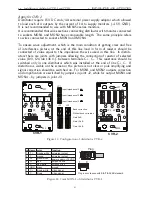
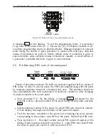
Video signal in CD-3100 system is sent by symetric line. This solution assures
of small sensibility of line for external interference. It also allows to send video
on relatively far distance but demends to comply with some rules with wiring
system.
In section between external panel and electronic cassette spiral wire of dia. min.
0.5 mm and impedance 100
Ω
should be used. Minimal number of entry phone
wires amounts 18 for entry phone without gateway drive control and 20 with
gateway control.
Section: external panel - electronic cassette should be made of telecommu-
nication cable or UTP spiral (e.g. XzTKMXpw, YTKSY, UTP cat.5, LAN
T11).
Section: electronic cassette - distributor CVR-1 should be made of UTP spiral
cat.5 or telecommunication spiral (e.g. YTKSY).
Section between distributor and monitors should be made using spiral UTP
cat.5. In case of CVR-1 plugs RJ45 should be installed on wire ends at the
distributors (according to the instruction).
Total length of a segment electronic cassette – distr distributor –
monitor should not exceed 150m.
Attention should be paid to appropriate matching of cables pairs. In the dia-
gram, any pair of cables is marked with lines (thick and thin ones), which are
situated close one to each other.
17

