6.9 Installation of monitor and additional cameras
6 INSTALLATION AND ACTIVATION
6.9
Installation of monitor and additional cameras
Installation and connection of monitors and additional cameras should be made
on the basis of instruction enclosed to models that were used.
6.10
Installation and programming of uniphone
We assume that for each apartment a uniphone connection wire is routed, this
wire is connected to terminals L+, L- of the exchange and the line is not shorted.
Prior to installation of a uniphone its cover should be removed. Uniphone base
should be fixed to the wall with strut pins
6 mm using openings in the uniphone
base. Next uniphone number should be programmed. It is allowed to program at
the most two uniphones (or monitors) with the same number. Programming is done
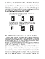
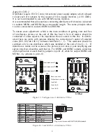
by proper configuration of jumpers in joint inside uniphones. In uniphone physical
number is programmed. Each number from a range 1...255 can be presented as
a sum of numbers 1, 2, 4, 8, 16, 32, 64, 128. If a digit is included in the sum of
the programmed number then we put a jumper in a position which corresponds to
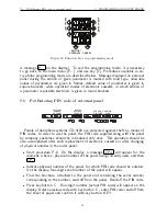
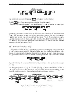
it, otherwise jumper should be removed (see dwg. 15).
Number ”0” should not be programmed (removal of all jumpers)!
On uniphone plate are marked digits assigned to consecutive positions on the joint.
Example: in order to program number 37, jumpers should be put on interfaces in
positions 1, 4, 32 (1+ 4 + 32 = 37). Then wires should be connected to uniphone
terminals paying attention to their appropriate polarization and the uniphone casing
should be closed. Uniphone is ready for operation and it can be checked using
procedure P-3.
a)
37 = 1 + 4 + 32
1 2 4 8 16 32 64 128
1 2 4 8 16 32 64 128
b)
Figure 15: View of interface used for programming uniphone and example illustrating program-
ming of uniphone to number 37.
Assembly and installation of non-standard uniphones, performing additional func-
tions, such as LM-8W/4 or LG-8 should be carried out in accordance with a manual
attachable to such equipment.
6.11
Adjustment of the doorphone system CD-3100
Initial adjustment of the doorphone is completed already during the production
process. In some cases it could be necessary to make adjustments with the purpose
to adjust parameters to real working conditions taking into consideration noise levels
in places, where the outer panel will be installed, or requirements of its users.
The doorphone is provided with the following potentiometers:
potentiometer P1 in the panel used to adjust signal amplification in loudspeaker
of the panel.
24

