15 SELECTION OF WIRES AND CONNECTION DIAGRAMS
CS
V+
G
A
L-
L+
L+
L-
CS
VS
GS
MC
GA
SP
T
-
GS
VZA
GZA
MC
GA
SP
T
GS
KZ
GZ
PANEL 1
Electro-catch
EC-3100/H
CVP-2
MRL-1 module
VS
VS
CP-31xx
C2+
C2-
MC
MG
SG
SP
T
GD
VS
VZ
GZ
C+
C-
MC1
GA1
SP1
T1
XZ
V
S1
KZ1
GS1
MC
MG
SG
SP
T
GD
C+
C-
GZ
VZ
VS
XZ
+
-
C2+
C2-
C3+
C3-
C4+
C4-
MC2
GA2
SP2
T2
GS2
230 V AC
14,5 V AC
0,8 A
12 V AC
1 A
White
Brown
AC4
AC3
AC2
AC1
Brown
Brown
Electronic
cassette
power
supply
PANEL 2
Electro-catch
CP-31xx
X+
X-
Y+
Y
-
C+
C-
L-
L+
T+
T
-*
C1+
C1-
G
Z1
230V
C1+
C1-
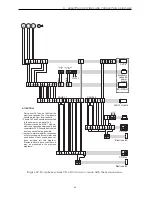
ATTENTION!
- Only panel Nr 1 can be fed from the
electronic cassette. The other panels
should be fed from local feeders.
- Panels Nr 3 and 4 should be connected
in the same way, as panel Nr 2.
- Electronic cassette, MRL-1 module,
electronic cassette power supply and
commutator CVP-2 should be mounted
as close each other as possible.
- In order to improve legibility, connection
of list of occupants, accumulator and
push-button of door opening has not
been included into this diagram.
Elements should be connected in a
way, as presented in the previous
diagrams.
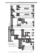
Figure 42: Doorphone system CD-3100 in video version with the main entrance
64

