4 - Operation
Page 09
4.3 - Leveling the Drill Bits
4.3.1
4.3.2
4.3.3
4.3.4
4.3.5
4.3.6
4.3.7
4.3.8
4.3.9
4.3.10
4.3.11
4.3.12
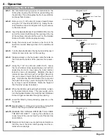
We recommend using a piece of card stock on the
Table when leveling the drill bits to avoid drilling into
the drill strip. This will lengthen the life of your drill bits
and keep them sharper.
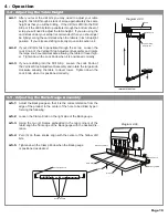
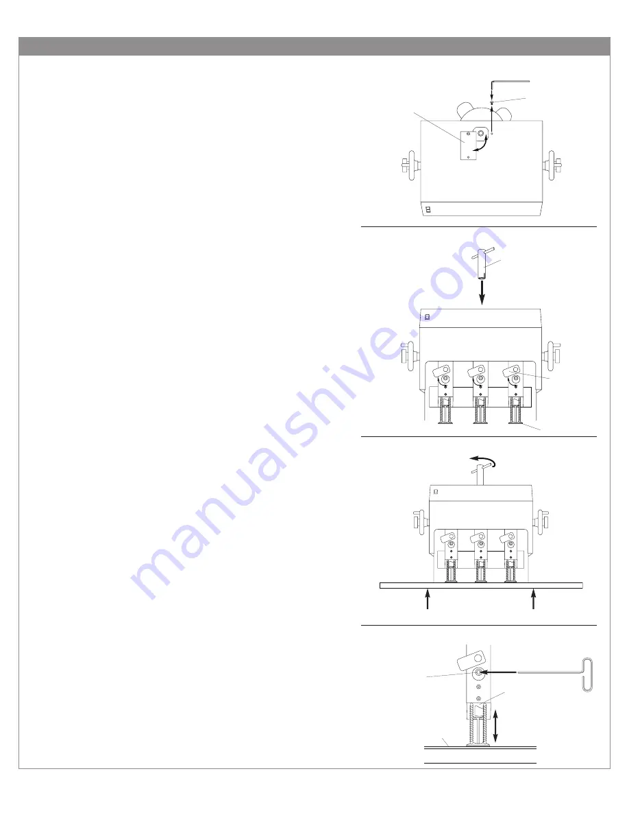
Remove one (1) of the two (2) Access Guard Screws
using the 1/8” Hex Wrench (HEX-18). Swing the Ac-
cess Guard as shown in diagram 4-40 to gain access
to the motor shaft.
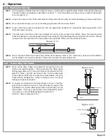
Insert the Spindle Rotation Tool (FMM9-957A) into the
end of the motor shaft through the opening in the top
of the machine shroud until the notch in the Spindle
Rotation Tool fits into the keyway securely.
Swing the access cover located on the front of the
heads to one side allowing access to the spindle and
chuck.
Turn the Spindle Rotation Tool by hand until the insert
retainer screw can be seen in the opening.
Stepping slowly on the foot pedal, raise the table so
that it meets the bottom of the pressure foot assem-
bly.
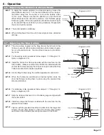
Using the 7/32” Hex Wrench (HEX-732-T), loosen
the insert retainer screw approximately one half turn
(loosening too much may cause the insert retainer
screw to come out completely). Retighten the insert
retainer screw until it is snug but not tight; this will al-
low you to raise or lower the chuck without too much
play. Hold onto the Spindle Rotation Tool to prevent
the belts from turning. Lower the height of the Chuck
by turning it counter-clockwise. Raise the height of
the Chuck by turning it clockwise.
When the drill bit is just touching the drill strip, re-tight-
en the insert retainer screw. This may require you to
turn the Spindle Rotation Tool until the Insert Retainer
Screw is again accessable through the opening.
Lower the table by slowly releasing pressure on the
foot pedal.
Repeat steps 4.3.4 through 4.3.9 on the remaing Drill
Bits so that they are all level with each other.
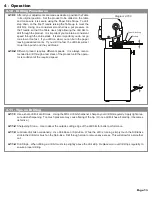
REMOVE THE SPINDLE ROTATION TOOL FROM
THE MOTOR SHAFT. Leaving this attached can
cause injury to the user as it can fly out of the machine
upon startup.
Replace all the Access covers and Access Guards so
that they cover the motor shaft opening and the re-
tainer screw openings.
Diagram 4-50
Diagram 4-40
Access Guard
1/8” Hex Wrench
Access Guard Screw
Table
Diagram 4-60
7/32 Hex Wrench
Insert Retainer
Screw
Chuck
Table
Card Stock
Diagram 4-70
Spindle Rotation Tool
Access Cover
Pressure Foot


