Initial Set-Up
Lift Arm Stop Bolt Adjustment
Initial Set-Up
Lastec//021819
3-3
3
3.3
Lift Arm Stop Bolt Adjustment
Danger
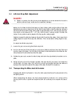
DANGER!
Failure to perform the lift arm stop bolt adjustment as recommended will result in
serious personal injury and/or severe equipment damage.
Make sure the tractor and the Articulator are level, before performing the lift arm stop bolt
adjustment procedure. Adjust each of the lift arm stop bolts so that the distance between
the stop bolt head and the edge of the plate is approximately 3/16”, if the mower deck cut-
ting height is set between 2.5” - 3.5” (the most common cutting height). Outside this
range, the stop bolts must be adjusted for the specific cutting height.
Slightly increase the distance between the stop bolt head and the plate, if the mower deck
cutting height is raised. Decrease the distance, if the mower deck cutting height is low-
ered.
To adjust the lift arm stop bolts:
1.
Loosen the jam nut securing the lift arm stop bolt.
2.
Turn the lift arm stop bolt clockwise to increase the distance between the stop bolt head
and the edge of the plate. Turn the lift arm stop bolt counterclockwise to decrease the dis-
tance between the stop bolt head and the plate.
3.
Tighten the jam nut to secure the lift arm stop bolt when the adjustment procedure is com-
plete.
4.
Slowly raise the unit to the transport position. Be sure the drive line does not contact the
mower deck. If it does, lower the unit to the ground and slightly decrease the distance
between the stop bolt head and the edge of the plate. Recheck for clearance.
3.4
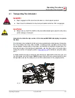
Transporting the Mounted Articulator
Engaging the tractor hydraulics to move the deck upward will raise the wing decks to the
transport position.
When transporting the decks, the front wheel should be minimum of 4 inches off the
ground, and 6 inches is preferred. Adjust the hitch as necessary to accomplish this eleva-
tion.
Summary of Contents for 100EFNH
Page 1: ...Lastec Mower 100EFNH Owner s Manual Manual Part Man 100EFNH...
Page 5: ...Lastec 021819 1 1 1 SECTION 1 TO THE OWNER...
Page 12: ......
Page 13: ...Safety Information Safety Information Lastec 021819 2 1 2 SECTION 2 SAFETY INFORMATION...
Page 25: ...Initial Set Up Initial Set Up Lastec 021819 3 1 3 SECTION 3 INITIAL SET UP...
Page 38: ...Lastec 021819 4 1 4 SECTION 4 OPERATING PROCEDURES...
Page 46: ...Operating Procedures Anti Scalp Wheel Adjustment 4 4 9 Lastec 021819 Operating Procedures...
Page 47: ...Maintenance Maintenance Lastec 021819 5 1 5 SECTION 5 MAINTENANCE...

