background image

Initial Set-Up

Mower Deck Leveling Adjustment

3

3-6

Lastec//021819

Initial Set-Up

3.8

Mower Deck Leveling Adjustment

Danger

DANGER!

Always stop the tractor and disengage the PTO before attempting to set or adjust 
the mower deck height!

Never adjust the mower deck height with the tractor running or the PTO engaged.

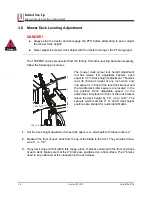
The 100EFNH comes pre-leveled from the factory. Should re-leveling become necessary, 
follow the following procedures. 

The mower deck wheel lock height adjustment 
rod has twelve (12) adjustable spacers, each 
equal to 1/4" of deck height adjustment. The deck 
is at its minimum height of one inch when only 
one spacer is in front of the lever lock bracket and 
the middle deck idler spacers are located in the 
top position. Each adjustable spacer on the 
adjustment rod placed in front of the lock bracket 
raises the deck height by 1/4”, up to 4-3/4”. The 
spacers which mark the 2", 3", and 4" deck height 
positions are knurled for quick identification.

1.

Set the deck height adjustment wheel lock spacers on all wheels with these locks to 2”.

2.

Measure the front of each deck from the tip of the blade to the floor. They should all mea-
sure 2”, +/- 1/8”.

3.

If any deck does not fall within this range, place 2” blocks underneath the front and back 
of each deck. Make sure that the 2” blocks are positioned on a flat surface. The 2” blocks 
need to be positioned at the closest point to each wheel.

100_135

Jam Nut

Summary of Contents for 100EFNH

Page 1: ...Lastec Mower 100EFNH Owner s Manual Manual Part Man 100EFNH...

Page 2: ...is manual may be reproduced in any form by any photographic electronic mechanical or other means or used in any information storage and retrieval system without written permission from Lastec LLC 8180...

Page 3: ...s And Covers 2 5 2 5 Pre operational Safety Rules 2 6 2 6 Operational Safety Rules 2 7 2 7 Maintenance Safety Rules 2 10 2 8 Storage Safety Rules 2 11 2 9 Hazard Identified Chart 2 12 SECTION 3 INITIA...

Page 4: ...reme Contours 4 7 4 8 Cutting Wet Grass 4 7 4 9 Anti Scalp Wheel Adjustment 4 8 SECTION 5 MAINTENANCE 5 1 5 1 Every 8 Operating Hours 5 2 5 2 First 8 Hours 5 3 5 3 First 50 Hours 5 3 5 4 Every 50 Oper...

Page 5: ...Lastec 021819 1 1 1 SECTION 1 TO THE OWNER...

Page 6: ...ulator when children are present The information presented herein will prepare you to operate the Articulator in a safe and knowledgeable manner Proper opera tion of the Articulator will provide a saf...

Page 7: ...ec com or located in the back of this section This form must be completed and returned to the fac tory within fifteen 15 days of purchase in order to validate the warranty Please do not hesitate 1 3 I...

Page 8: ...under warranty at the warrantor s discretion After ninety 90 days component fail ure as a result of loose hardware is no longer covered under further warranty from warrantor Warrantor agrees to warran...

Page 9: ...ales aids shall constitute a warranty or other basis for any legal action against warrantor THE ORIGINAL PURCHASER ANY PERSONS TO WHOM THIS EQUIPMENT IS TRANFERRED AND ANY INTENDED USER OR BENEFICIARY...

Page 10: ...ly engineered and manufactured to provide safe dependable and satisfactory service As with all other mechanical equipment the Articulator requires routine inspection cleaning and maintenance When serv...

Page 11: ...of purchase Mower Model How did you hear about Lastec Who referred you to Lastec Date Purchased Distributor Dealer Purchased From How Did You Hear About Us Your Lastec Mower Average Operating Hours To...

Page 12: ......

Page 13: ...Safety Information Safety Information Lastec 021819 2 1 2 SECTION 2 SAFETY INFORMATION...

Page 14: ...equipment hazard Failing to properly adhere to the instructions rules or procedures may result in personal equipment malfunction damage or destruction The above illustrated symbols are displayed thro...

Page 15: ...and Symbols Safety Information Lastec 021819 2 3 2 Caution Rotating Blades Keep Hands and Feet Away from Blades Keep Covers Locked Down Pinch Point Read the Manual Remove the Key Rotating Parts Rotati...

Page 16: ...in this manual as well as all safety rules for any related equipment Although these instructions have been compiled through extensive field experience and engineering data some information presented...

Page 17: ...r operate the deck without all covers shields safety devices and grass chute or mulching plate installed and secure Safety is a primary concern in the design and manufacture of all Lastec products Unf...

Page 18: ...the entire operator s manual to operate the deck Always wear relatively tight and belted clothing to avoid entanglement in moving parts Wear sturdy rough soled work shoes as well as protective equipm...

Page 19: ...nce against accidents ALWAYS clear area of all personnel before operating the deck Only allow persons who have read and understand the entire operator s manual to operate the deck Be sure that the par...

Page 20: ...d deck Use extreme care and maintain minimum ground speed when transporting on a hill side or over rough ground and when operating close to ditches fences or water Reduce speed on slopes and in sharp...

Page 21: ...nded If your drive unit is equipped with headlights and hazard lights always activate them whenever crossing or accessing any roadways driveways or parking lots Watch for oncoming traffic Handle fuel...

Page 22: ...ead and ear pro tection when performing any service or maintenance to the drive unit or deck Keep the drive unit engine area free of accumulated debris fuel or excess grease and oil to reduce fire haz...

Page 23: ...ngine indoors Exhaust fumes are deadly Never store drive unit with fuel in the tank inside a building where fumes could reach an open flame or spark Allow the drive unit engine to cool before storing...

Page 24: ...using a PTO Guards are not in place Warning decals stating guards must be in place Physical guards around belts pulleys and shafts Clear warning in manual Danger of dismemberment Cutting blades Warnin...

Page 25: ...Initial Set Up Initial Set Up Lastec 021819 3 1 3 SECTION 3 INITIAL SET UP...

Page 26: ...evel ground Be sure deck lift arms are in lowered position 2 Turn off the tractor disengage the PTO shift the transmission into neutral and set the parking brake Remove the key from the ignition 3 App...

Page 27: ...ower deck cutting height is low ered To adjust the lift arm stop bolts 1 Loosen the jam nut securing the lift arm stop bolt 2 Turn the lift arm stop bolt clockwise to increase the distance between the...

Page 28: ...shaft shorter or avoid this area when cutting 6 If the PTO shaft can be easily reconnected then your maximum compression is within the proper range of your PTO shaft Now you will need to check the ma...

Page 29: ...7 Mower Deck Height Adjustment The Model 100EFNH Articulator can be set to various heights ranging from 1 to 4 3 4 Change the mower deck height at all the wheel locations by moving the wheel spacers...

Page 30: ...inch when only one spacer is in front of the lever lock bracket and the middle deck idler spacers are located in the top position Each adjustable spacer on the adjustment rod placed in front of the l...

Page 31: ...onal or replacement spacers may be obtained from your Lastec dealer if necessary 5 Adjust the rear wheel lock spacers to remove any excess slack by loosening the jam nut adjusting the rod on wheel loc...

Page 32: ...erly adjusted they can fail within a few hours Be aware that over 50 of the total belt stretch will occur within the first few hours of use The deck drive belts are located between the gearbox and the...

Page 33: ...on after 2 hours of operation Check all belt tension adjustment hardware after the first 8 hours of operation Again the overall life of the Articulator drive and deck belts is more greatly affected by...

Page 34: ...lator If you are unable to install a new belt with the idler system at its minimum stroke it is likely you are installing the wrong size belt Contact your Lastec dealer for proper belt lengths for you...

Page 35: ...to the blades while the engine is running ALWAYS disengage the blades turn off the tractor remove the key and set the parking brake before attempting to inspect adjust change or perform any other mai...

Page 36: ...t swivel freely clean and grease the shaft collar assembly Replace the bushings if necessary Grease each wheel after 8 hours of use and replace any worn or damaged tires 3 13 General Verify that all w...

Page 37: ...n Clean the entire center deck area including under the belt cover of all grease oil fuel grass or debris Be sure to replace all covers shields and guards Check all deck belts for proper tension Clean...

Page 38: ...Lastec 021819 4 1 4 SECTION 4 OPERATING PROCEDURES...

Page 39: ...raulics to fold up the two outside decks allowing easy transporta tion This feature has many other benefits including remote operation access across narrow bridges through gates or doorways and reduct...

Page 40: ...leveled from the Lastec factory Should deck leveling be necessary during maintenance see the section on Mower Deck Leveling Adjustment in the Set Up section of this manual 1 Disengage the PTO DANGER...

Page 41: ...culator The Articulator is designed specifically for finish mowing applications One of the unique benefits of the Articulator s cutting system is its ability to float over contours that are impossible...

Page 42: ...g brake and carefully begin cutting 4 4 Recommended Blades Ultra Low Blade Part No 063265 Use Ultra Low Lift Blade when the conditions are dry and in sandy soil areas When con ditions like this are ev...

Page 43: ...5 MPH Your speed may vary within this range as your cutting conditions vary Excessive ground speed while trav eling over rough terrain can cause the Articulator to bounce excessively which in turn in...

Page 44: ...rticulator will be able to handle the area When cutting extreme contours always use a drive unit equipped with a ROPS and always wear your seat belt Following are important guidelines to follow when c...

Page 45: ...ANT Any time the mower deck height is adjusted on the Articulator it is neces sary to check all the anti scalp wheels for proper positioning The recommended anti scalp wheel height settings are as fol...

Page 46: ...Operating Procedures Anti Scalp Wheel Adjustment 4 4 9 Lastec 021819 Operating Procedures...

Page 47: ...Maintenance Maintenance Lastec 021819 5 1 5 SECTION 5 MAINTENANCE...

Page 48: ...ware is functional securely fastened and in good condition Grease all wheel hubs Grease the PTO shaft collar and both cross bearings Inspect all belts for cracks wear or damage replace as needed Inspe...

Page 49: ...gearbox lube with 75W 90 gear oil 5 4 Every 50 Operating Hours Check deck alignment and belt tension Check deck drive belt alignment Grease all blade spindle bearing housings Fill until grease purges...

Page 50: ...ns Model 100EFNH Mower Deck Configuration 5 21 Articulating Mower Decks Cutting Width 100 Blades 5 21 High Lift P128 5 21 Low Lift P246 5 21 Mulching Blades P322 5 21 Low Lift Ultra 063265 Blade Tip S...

Page 51: ...ls or Other Hazards Perform the Appropriate Maintenance Procedures Listed In Your Tractor Manual Verify grass chutes cleared Clean lube retighten all guide wheels Lubricate the PTO Quick Disconnect Pi...

Page 52: ...18 10 16 9 14 8 in lbs Nm in lbs Nm in lbs Nm in lbs Nm in lbs Nm in lbs Nm in lbs Nm ft lbs Nm ft lbs Nm ft lbs Nm ft lbs Nm ft lbs Nm ft lbs Nm ft lbs Nm ft lbs Nm ft lbs Nm ft lbs Nm ft lbs Nm ft...

Page 53: ...Maintenance Lastec 021819 5 7 5 5 11 Lubrication Points Model 100EFNH See Figure 5 1 The Articulator lubrication points are shown below Idler Idler Idler 100_050 IMPORTANT Each wheel also has a fitti...

Page 54: ...rt ant that the spacers remain tight between the frame work at all times Failure to keep these spacers tight will result in premature wear on the bolts and equipment damage Ensure that ALL bolts assoc...

Reviews: