background image

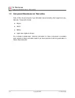
1.7

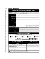
Warranty Registration

Company Name

Company Contact

Mailing Address

Shipping Address

Phone

Fax

Authorized Company

Representative Signature:

Detatch Here

Detatch Here

Detach Here

   Serial Number:

Please check the box that most accurately describes your business:

                    Please check the box to your left if you would not allow Lastec to use your company's name for marketing purposes.

Lastec Warranty Registration Form

IMPORTANT!

  To validate the warranty, this registration form must be completed in full and returned to Lastec within 

fifteen (15) days of purchase!

       Mower Model:

How did you hear about Lastec?

Who referred you to Lastec?

Date Purchased:

Distributor/Dealer Purchased From:

How Did You Hear About Us?

Your Lastec Mower

Average Operating Hours:

Total Acreage Cut:

Customer Profile Information

I have read and understand the warranty policy 

and maintenance sections of the operators 

manual for the machine described below.

Who was the salesman that assisted you?

Please help us to better serve you by completing the following survey 

information:

Please list the features and/or benefits which 

helped you to choose your Lastec Mower:

Do you own a Lastec Mower, and if so what model?

Purchase Price:

Golf Course

Municipal

Sod Farm

Government

Sports Complex

Other

Weekly

Weekly

Monthly

Monthly

Annually

Annually

Schools

College

Landscaping Company

Light Agriculture

Summary of Contents for 4520ZSR

Page 1: ...LASTEC 7865 N County Road 100E Lizton Indiana 46149 Phone 317 892 4444 Fax 317 892 4188 www lastec com Lastec Mower 4520ZSR Owner s Manual Manual Part Man 4520ZSR...

Page 2: ...ronic mechanical or other means or used in any information storage and retrieval system without written permission from Lastec Inc 7865 N County Road 100E Lizton IN 46149 CALIFORNIA Proposition 65 War...

Page 3: ...Manufacturers Warranties 1 6 1 6 Servicing The Articulator 1 7 1 7 Warranty Registration 1 8 SECTION 2 SAFETY INFORMATION 2 1 2 1 Warning Symbols 2 2 2 2 Safety Decals and Symbols 2 2 2 3 About This...

Page 4: ...13 3 13 Blades 3 14 3 14 Operator Seat 3 15 3 15 Steering Column Tilt Adjustment 3 16 3 16 Mower Deck Height 3 17 3 17 Mower Deck Height Calibration 3 18 3 18 Tires and Wheels 3 20 3 19 General Inspec...

Page 5: ...s 5 3 5 5 Every 100 Operating Hours 5 3 5 6 Every 200 Operating Hours 5 3 5 7 Every 400 Operating Hours 5 4 5 8 Every 500 Operating Hours 5 4 5 9 Annual 5 4 5 10 Bi Annual 5 4 5 11 Maintenance Schedul...

Page 6: ......

Page 7: ...Lastec 020515 1 1 1 SECTION 1 TO THE OWNER...

Page 8: ...ulator when children are present The information presented herein will prepare you to operate the Articulator in a safe and knowledgeable manner Proper opera tion of the Articulator will provide a saf...

Page 9: ...ec com or located in the back of this section This form must be completed and returned to the fac tory within fifteen 15 days of purchase in order to validate the warranty Please do not hesitate 1 3 I...

Page 10: ...rranty at the warrantor s discretion After ninety 90 days component fail ure as a result of loose hardware is no longer covered under further warranty from warrantor Warrantor agrees to warrant for a...

Page 11: ...ales aids shall constitute a warranty or other basis for any legal action against warrantor THE ORIGINAL PURCHASER ANY PERSONS TO WHOM THIS EQUIPMENT IS TRANFERRED AND ANY INTENDED USER OR BENEFICIARY...

Page 12: ...ent parts of your Articulator are warranted by their respective manu facturers These parts include Engine Clutch Battery Hydro Gear Hydraulic Pumps The complete manufacturers warranty information for...

Page 13: ...servicing the Articulator be sure to use only genuine Lastec parts Utilization of substitute parts will not only void the warranty but may also cause unsafe or unsatisfac tory operation of the Articul...

Page 14: ...u hear about Lastec Who referred you to Lastec Date Purchased Distributor Dealer Purchased From How Did You Hear About Us Your Lastec Mower Average Operating Hours Total Acreage Cut Customer Profile I...

Page 15: ...Lastec 020515 2 1 2 SECTION 2 SAFETY INFORMATION...

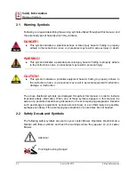
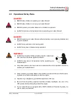
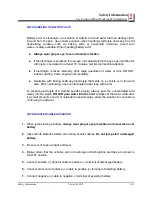
Page 16: ...es a potential equipment hazard Failing to properly adhere to the instructions rules or procedures may result in personal equipment malfunction damage or destruction The above illustrated symbols are...

Page 17: ...and Symbols Safety Information Lastec 020515 2 3 2 Caution Rotating Blades Keep Hands and Feet Away from Blades Keep Covers Locked Down Pinch Point Read the Manual Remove the Key Rotating Parts Rotati...

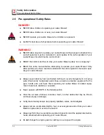
Page 18: ...rules in this manual as well all safety rules for any related equipment Although these instructions have been compiled through extensive field experience and engineering data some information present...

Page 19: ...mational purposes only NEVER operate your Lastec Mower with any of the safety covers removed Safety is a primary concern in the design and manufacture of all Lastec products Unfortunately our extensiv...

Page 20: ...s who have read and understand the entire operator s manual to oper ate your Lastec Mower Always wear relatively tight and belted clothing to avoid entanglement in moving parts Wear sturdy rough soled...

Page 21: ...WARNING ALWAYS work safely Follow all safety rules A careful oper ator is the best insurance against accidents ALWAYS clear area of all personnel before operating your Lastec Mower Only allow persons...

Page 22: ...in sharp turns to minimize potential tipping or loss of control Use caution when changing directions on slopes Be alert for holes in the terrain as well as any other hidden hazard Always drive slowly...

Page 23: ...r accessing any roadways driveways or parking lots Watch for oncoming traffic Do not allow extended running of engine indoors exhaust fumes are deadly Handle fuel with caution Always use approved fuel...

Page 24: ...protection when performing any service or maintenance Keep your Lastec Mower engine area free of accumulated debris fuel or excess grease and oil to reduce fire hazard Keep your Lastec Mower in good o...

Page 25: ...en Never allow extended running of the engine indoors Exhaust fumes are deadly Never store equipment with fuel in the tank inside a building where fumes could reach an open flame or spark Allow the en...

Page 26: ...ith clean water A solu tion of baking soda or household ammonia and water may be used as a neutralizer Electrolyte splashed into the eyes is extremely dangerous If this should happen force the eye ope...

Page 27: ...a any electrolyte that spills on a vehicle or in the work area After neutralizing rinse contaminated area clean with water To prepare electrolyte of a desired specific gravity always pour the concentr...

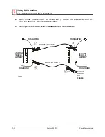
Page 28: ...INAL CONNECTION OF NEGATIVE CABLE TO ENGINE BLOCK OF STALLED VEHICLE AWAY FROM BATTERY 9 Start engine and remove cables in REVERSE order of connections 1 STALLED VEHICLE BATTERY TO GROUND ENGINE BLOCK...

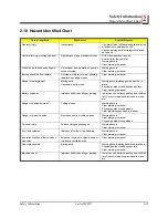
Page 29: ...elts and pulleys Clear warning in manual Battery explosion Improper battery handling or jumping Instructions on battery handling from the Bat tery Council International included in manu als Danger of...

Page 30: ......

Page 31: ...Lastec 020515 3 1 3 SECTION 3 INITIAL SET UP...

Page 32: ...pped with the baffles and mulching plates installed to the deck 3 and the deck 5 Remove the appropriate baffles and or mulching plates to discharge the grass to the side or to the rear before starting...

Page 33: ...arking brake is located to the left of the operator seat To set the parking brake grasp and pull the handle increasing the brake tension until the tension prevents any fur ther travel of the handle To...

Page 34: ...Lastec Mower is shipped dry no fuel from the factory so you will need to fuel the Lastec Mower before operating The engine has been run at the fac tory so bleeding the fuel lines is unnecessary The fu...

Page 35: ...handle on the right side of the seat to unlock and lift the seat pan assembly See Section 3 14 for more information on the seat opera tion Engine cover hood Release the two fasteners located at the t...

Page 36: ...the oil level and quality be checked daily Use of incorrect oil inadequate oil level or con taminated oil will cause engine damage Be sure the Lastec Mower is parked on level ground before checking th...

Page 37: ...re are two filter elements within the air cleaner The cap located on the rear of the air cleaner is opened by unlatching both silver latches located on the sides of the filter housing Check that both...

Page 38: ...The radiator is located behind the operator s seat Overheating may occur if the radiator is not cleaned daily Brush out and clean the radiator screen daily to prevent overheating Check the coolant le...

Page 39: ...ns 2 2 1 2 gallon reusable containers of oil and 2 oil filters This is enough oil and filters for 2 complete hydraulic system oil changes system capacity is approximately 7 quarts The 5 gal hydraulic...

Page 40: ...uctions below for the proper procedure 1 Locate the bypass valve This will be located on the side of each pump NOTE The bypass valve is zinc plated with the hole drilled through the sides 2 Use a 5 8...

Page 41: ...the belt Check the belt for 35 lbs tension If the idler tensioner rotates to its maximum stroke with out adequately tightening the belt you need to replace the belt If the belt you are checking is new...

Page 42: ...oves to its maximum stroke with out adequately tightening the belt you need to replace the belt If the belt you are check ing is new and the idler tensioner goes to its maximum stroke without adequate...

Page 43: ...adequately tightening the belt you need to replace the belt If the belt you are check ing is new and the idler tensioner slides to its maximum stroke without adequately tightening the belt it is likel...

Page 44: ...ne remove the key and set the parking brake before attempting to inspect adjust change or perform any other maintenance to the blades Keep all personnel clear of all controls while inspecting adjustin...

Page 45: ...ly latched and operator seat is secure Be sure the seatbelt is secure and operable Adjust the seat forward or back so that the operator can easily reach the steering wheel with the control panel foot...

Page 46: ...lumn can be tilted towards or away from the operator seat as needed To tilt the steering column grasp the steering wheel and press the tilt lock foot pedal located on the left side of the steering col...

Page 47: ...deck height five adjustment points must all match each other Start with the center deck Push the deck height control foot lever outward relieving the tension on the adjustment rod Set the 1 4 spacers...

Page 48: ...When you receive your Lastec mower you may need to calibrate the mower deck height Follow these procedures to calibrate 1 Park your Lastec Mower on a flat level surface Be sure to turn off the engine...

Page 49: ...aking measurements If adjustments are needed on the center deck use the jam nut on the center adjustment rod on the deck lift assembly Tolerances for front to back is positive 1 8 inch in the rear the...

Page 50: ...djust replace and grease as necessary Check that each wheel swivels freely in the shaft pivot collar and the bearings are in good condition If any wheel does not swivel freely clean and grease the sha...

Page 51: ...accelerates makes any abnormal noises runs roughly or displays any other usual characteristics stop the engine and correct the problem before operating your Lastec Mower 3 21 Hour Meter The hour meter...

Page 52: ...r debris Check all mower deck belts and idler tension springs for proper installation tension and condition Clean each deck of any grease oil fuel grass or debris Inspect all blades for proper install...

Page 53: ...Lastec 020515 4 1 4 SECTION 4 OPERATING PROCEDURES...

Page 54: ...anyone to operate the Lastec Mower without proper training and with out first reading and understanding this manual in its entirety CAUTION ALWAYS perform the pre operation equipment inspection befor...

Page 55: ...e key switch clockwise to START position cranking the engine for a maximum of 10 seconds NOTE Cranking engine for more than 20 seconds will cause electrical failure 3 If the engine does not start with...

Page 56: ...fy that all safety covers are in place and secure before operating the Lastec Mower Buckle the seatbelt Always wear the seatbelt when operating the Lastec Mower Clear the entire area of all personnel...

Page 57: ...Lastec Mower travels To turn to the right Turn the steering wheel clockwise slowly To turn to the left Turn the steering wheel counterclockwise slowly To obtain a zero turn radius ZTR to the right Put...

Page 58: ...s are evident lift created by the cutter blades can be reduced decreasing the abrasion wear to the cutter blades and deck caused by sand The Low Lift Blade will also help reduce cutter deck blowout du...

Page 59: ...only and should not be attempted during any cutting operation Attempting to change directions at high ground speed whether cutting or transporting can cause damage to the turf especially in wet condi...

Page 60: ...ruise control toggle switch toward the operator and hold Press the foot pedal to set the mower to the desired speed and release the foot pedal Release the cruise control toggle switch To reset the cru...

Page 61: ...vailable positions 180 or 360 degrees When the lock is in the 180 degrees position turning the steering wheel all the way clockwise or counterclockwise will result in the mower making turns as shown b...

Page 62: ...and three deck belts running between the decks drive each deck The individual decks pivot at blade level and the idler belt tension system takes up excess belt length or releases additional belt lengt...

Page 63: ...pulley Under normal operating situations the pulley should not be changed from the factory set position However in order to help the idler pulley keep proper tension on a drive belt 40 50 ft lbs on t...

Page 64: ......
Page 65: ...Lastec 020515 5 1 5 SECTION 5 MAINTENANCE...

Page 66: ...er unsafe operating conditions substan dard performance and will void the warranty Warranty issues are dependent upon proper maintenance Along with completing the Pre Operation Equipment Inspection Ch...

Page 67: ...g air 5 3 First 50 Operating Hours Change the hydraulic oil and filter Change engine oil and filter 1 5 4 Every 50 Operating Hours Inspect engine fuel lines and clamps Replace as needed 1 Grease all b...

Page 68: ...ush fuel tanks 2 Flush radiator 2 Replace engine fan and alternator belts 2 Check engine valve clearance2 Check head mounting bolt torque while doing valve check 2 5 9 Annual Replace air cleaner filte...

Page 69: ...X X X X X X X X Verify proper installation operation and flow of grass chute X X X X X X X X X Inspect entire Lastec Mower for loose or entangled parts debris obstructions neglected tools or other ha...

Page 70: ...Main Drive Belt Belt C138 Mule Drive 063211 Deck Drive Belts Center Belt 72 Deck Drive 048272 Wing Deck Right Belt Insta Power 85890 P706 Wing Deck Left Belt Insta Power 85950 063879 Maximum Forward S...

Page 71: ...on Ratio 21 1 Dry Weight 251 lbs Oil API Service Class CJ 4 Shell Rotella T SAE 10W 30 Oil Capacity w Filter Approx 7 1 US qt 6 7L Oil Filter Kubota 16271 32090 018050 Fuel Diesel Fuel No 2 D ASTM D97...

Page 72: ...Lastec 020515 Maintenance 5 15 Hydraulic System Diagram FIG 5 1 ZSR022 3 Right Tank Left Tank Coolers Lift Valve Left Motor Right Motor Right Cylinder Left Cylinder Deck Lift Collar Steering Amplifie...

Page 73: ...se Assembly 1 2LPx80In ORFS 8 ST 1 9 072233 1 1 Replaced 1 071882 1 2LPx18In ORFS 8 90 Hose Assembly 10 13 Hose Assembly 5 8LPx21In ORFS 10 90 1 10 071883 Hose Assembly 1 2LPx12 1 2In ORFS 8 90 1 11 0...

Page 74: ...Off On Start Key Switch CR4 CR3 CR7 CR7 30 87 CR1 30 87 85 86 CR2 30 87 CR4 Oil Press Water Temp Glow 30 87 30 87A Water Temp Sender Alternator Alternator EX Alternator Blade C Blade B CR1 CR8 30 87...

Page 75: ...15 5 11 5 5 17 Lubrication Charts 4520ZSR FIG 5 3 LUBRICATION POINTS 120 DECK ASSEMBLY NOTE All wheels should also be lubricated every 8 hours of operation FIG 5 4 LUBRICATION POINTS MODEL 4520ZSR ZSR...

Page 76: ...ortant that the spac ers remain tight between the framework at all times Failure to keep these spacers tight will result in premature wear on the bolts and equipment damage Ensure that ALL bolts asso...

Page 77: ...in the straight forward position Check if the rear bolt and nut on the upper cam of the lower steering shaft are in the position as shown below STEP 2 STEP 2 STEP 3 COURSE ADJUSTMENT BY GEAR TOOTH ST...

Reviews: