background image

To The Owner

Component Manufacturers’ Warranties

To The Owner

8/18/20

1-5

1

RIGHTS OF PURCHASER 

The validity and effect of this limited warranty as well as its interpretation, operation and 
effect, shall be determined exclusively by the principles of law and equity of the State of 
Indiana. This limited warranty gives purchaser specific legal rights. Purchaser may also 
have other rights, which may vary from State to State. Some States may not allow limita-
tions as to duration of warranties so the above may not apply. 

This contract supersedes all prior written and oral agreements related to the purchase 
and is intended to be an integration of the entire agreement between the parties. All of the 
promises, warranties, guarantees and representations made by warrantor or its represen-
tatives that are not specifically contained herein are not included in this warranty.

1.7

Component Manufacturers’ Warranties

Some of the component parts of your Lastec Mower are warranted by their respective 
manufacturers. These parts include:

Engine

Clutch

Hydraulic pumps

Battery

The complete manufacturers’ warranty information for these components is available 
upon request. Contact your Lastec dealer if you have questions concerning warranties on 
these component parts.

Summary of Contents for D3700

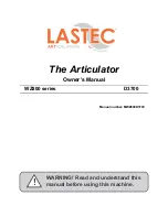
Page 1: ...WARNING Read and understand this manual before using this machine The Articulator Owner s Manual WZ800 series D3700 Manual number MWZ800D3700...

Page 2: ...ianapolis IN 46214 Phone 317 892 4444 800 515 6798 www lastec com DOLIRUQLD 3URSRVLWLRQ DUQLQJ 51 1 UHDWKLQJ JDV GLHVHO HQJLQH H KDXVW H SRVHV RX WR FKHPLFDOV NQRZQ WR WKH 6WDWH RI DOLIRUQLD WR FDXVH...

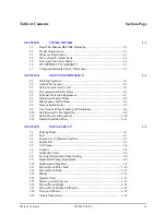
Page 3: ...7 Maintenance Safety Rules 2 6 2 8 Storage Safety Rules 2 7 2 9 Use Caution When Working With Batteries 2 8 2 10 Safe Booster Cable Operation 2 9 2 11 Safety Decals and Symbols 2 10 2 12 Hazard Ident...

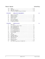
Page 4: ...Operation 4 18 4 8 Transporting the Mower 4 19 SECTION 5 MAINTENANCE 5 1 5 1 Maintenance 5 1 5 2 Every 8 Operating Hours or Daily 5 1 5 3 First 25 Operating Hours 5 2 5 4 First 50 Operating Hours 5 2...

Page 5: ...g to set up operate adjust per form any maintenance on or store the mower Keep this manual at hand at all times for ready reference 1 2 Product Registration Immediately record the model and serial num...

Page 6: ...Mower NOTE Use only genuine Lastec parts when servicing your Lastec Mower Use of substitute parts may cause unsafe operation unsatis factory performance and void the warranty of your Lastec Mower 1 5...

Page 7: ...tires bushings and blades for ninety 90 days from date of purchase After ninety 90 days all wear components are no longer covered under further warranty from warrantor Component failure as a result o...

Page 8: ...warranty The service department will issue an RMA number The part must be returned within 30 days of the requested return date Parts not returned within 30 days of the RMA issue date will result in r...

Page 9: ...act supersedes all prior written and oral agreements related to the purchase and is intended to be an integration of the entire agreement between the parties All of the promises warranties guarantees...

Page 10: ...nual in order to indicate important safety information When one of these symbols appears in this manual be aware of a potential hazard being discussed in the accompanying paragraphs Hazards such as da...

Page 11: ...ng application NOTE The illustrations and data used in this manual were current at the time of printing but the mower may vary slightly due to ongoing engineering changes Lastec reserves the right to...

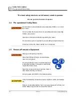
Page 12: ...e the mower without proper instruction Know how to stop the mower quickly in an emergency 2 5 Personal Protection Equipment Wear eye and hearing protection Wear close fitting clothing to avoid entangl...

Page 13: ...do not fuel the drive unit while the engine is hot do not fuel the mower indoors do not fuel while sitting on drive unit clean up any spilled fuel do not smoke around fuel or while fueling do not open...

Page 14: ...stments to the mower Stop the mower immediately upon striking any obstruction Disengage the blades turn off the engine set the parking brake remove the key and inspect the mower for any damage Repair...

Page 15: ...is properly mounted set up adjusted and in good operating condition Perform the pre operation equipment inspection and the appropriate maintenance schedule Section 5 before operating the mower Diseng...

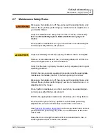
Page 16: ...le and legible Remove all tools and waste from the maintenance area 2 8 Storage Safety Rules Do not run the engine in an enclosed space Do not store equipment with fuel in the tank inside a building w...

Page 17: ...MPONENTS LEAD SUL FURIC ACID per SDS Safety Data Sheet EYE CONTACT Sulfuric Acid and Lead Flush eyes immediately with large amounts of water for at least 15 minutes while lifting lids Seek immediate m...

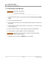
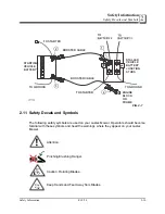
Page 18: ...that the two vehicles are not touching and both ignition switches are turned to the OFF position 4 Connect positive booster cable to positive junction studs on the inside front right side of the engi...

Page 19: ...ors should become familiar with these symbols and heed the warnings where they appear on your Lastec Mower Attention Pinching Crushing Danger Caution Rotating Blades Keep Hands and Feet Away from Blad...

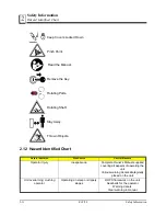
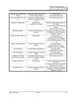
Page 20: ...12 Hazard Identified Chart Hazard Identified Risk Source Control Measure Operator injury Inexperience Complete Owner s Manual supplied covering all aspects of operating the unit Various warning decals...

Page 21: ...mberment Cutting blades Warning decals Clear warning in manual Physical guards around blades Clear prohibitions outlined in man ual Danger of projectile strike Ejected debris from cutting blades Warni...

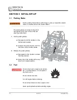
Page 22: ...e a Pull upward until the handle is in the full rearward position b Increase the brake tension until fur ther travel of the handle ceases 2 Release the parking brake a Pull upward on the handle to rel...

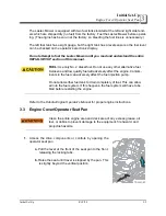
Page 23: ...native fuel Kerosene and low quality fuel will adversely affect the engine Contam inants in the fuel can adversely affect the fuel injection pump Do not allow either fuel tank to drain completely of f...

Page 24: ...ver are closed latched and secure 3 4 Engine Oil Turn off engine before checking the oil level changing the oil or changing the oil filter Allow ample time for oil to cool before changing or repairing...

Page 25: ...n the sides of the filter housing There are two filter elements within the air cleaner 1 Ensure both filter elements are clean and free of debris 2 Clean or replace if necessary 3 Consult the Kubota D...

Page 26: ...ind the operator s seat Consult the Kubota Diesel Engine Operator s Manual or proper coolant types and mixtures 1 Ensure engine is off and cool 2 Clean out any dirt or debris from around the radiator...

Page 27: ...rts 6 Re fill the coolant system with premixed coolant before operating 3 7 Hydraulic Fluid Hydraulic fluid is pressurized when hot Keep well away from any leaks or loose connections while system is p...

Page 28: ...approximately 5 quarts The 5 gal hydraulic oil kit part number is 049928 A 2 5 gal hydraulic oil kit part number is 049929 A quart of hydraulic fluid part number is 040642 1 Check the hydraulic fluid...

Page 29: ...e drilled through the sides 1 Use a 5 8 wrench to turn the valves no more than 2 two turns in a counterclockwise motion NOTE The drive tires should rotate freely 2 Tow the unit to the desired destinat...

Page 30: ...djust the hydrostatic pump link arm for that tire a Loosen the jam nut from the hydrostatic pump link arm b Slowly turn the link arm watch ing the tire as it turns c If the tire begins turning faster...

Page 31: ...r belts may not meet the all the demands leading to premature wear and reduced per formance Ensure that the idler tensioning spring is properly installed and in good condition If this spring becomes l...

Page 32: ...ed 3 12 Mower Deck Belts Do not inspect adjust or change the deck drive belt while the engine is running Clean the entire deck area under the operator seat pan of all grease oil fuel grass or debris t...

Page 33: ...ng or performing maintenance to the blades The Lastec Mower utilizes high lift blades 1 Inspect all blades for proper installation orientation tightness sharpness and overall condition 2 Tighten the b...

Page 34: ...a Swing the levers toward the operator seat removing them from the neutral lock position b Slowly push both levers all the way forward then all the way back 2 Ensure they both move smoothly and easily...

Page 35: ...deck changes before operating the mower All adjustment points must be set to the same height Center deck 1 Push the deck height control foot lever outward or use the adjustment tool stored next to the...

Page 36: ...e are a total of 6 spacers and 2 spacers With no spacers on the bottom area the deck will be set at 1 height of cut 1 Remove the top retaining pin 2 Remove the top washer 3 Allow the caster assembly t...

Page 37: ...ould not require frequent adjust ment However fine adjustment is available if warranted 1 Loosen do not remove the yoke mounting bolts 2 Loosen the jam nut on the adjustment bolt 3 Set the adjustment...

Page 38: ...arward taking the pressure off of the retaining pin 3 Remove the retaining pin 4 Rotate the adjusting plate so that the desired height of cut holes are aligned NOTE There is a reference decal for dete...

Page 39: ...running Set the parking brake before making any adjustments to your Lastec Mower When you receive your Lastec mower you may need to calibrate the mower deck height 1 Park your Lastec Mower on a flat...

Page 40: ...nd 5 require no calibration 3 18 Tires and Wheels 1 Check the air pressure in the rear drive tires 2 Maintain air pressure at 18 psi or as needed to maintain level deck cutting 3 Verify proper functio...

Page 41: ...total hours on the engine and cannot be reset You may wish to record the hour meter reading prior to oper ation for tracking of maintenance schedules job timing billing or other records 3 22 Maintena...

Page 42: ...sition Ensure both steering control levers are properly linked free of debris and operating freely Set the mower deck height to the desired level Calibrate the mower deck height adjustment rods if nee...

Page 43: ...drugs Wear eye and ear protection during operation Wear the seat belt during operation Do not allow children to operate this machine or be in the area when operating TERRAIN Inspect the area where the...

Page 44: ...d remove any fuel soaked debris imme diately TRANSPORT Use properly secured full width ramps for loading and unloading your Lastec Mower for transport Ensure ramps are a maximum of 15 degrees of slope...

Page 45: ...ttle Blades PTO ON OFF ENGINE CONTROLLER monitors and controls engine functions See 4 4 Engine Controller for complete instructions concerning the controller The Up Down buttons also act as alternate...

Page 46: ...S two USB chargers for operator s convenience ENGINE THROTTLE controls the engine speed PTO BLADES ON OFF engages disengages the cutting blades 4 2 Starting The Engine The following safety conditions...

Page 47: ...ments NOTE Do not overpower the engine 4 3 Stopping The Engine 1 Stop the engine by throttling down to a slow idle 2 Turn the ignition key switch to the OFF STOP position 3 Wait for all motion to stop...

Page 48: ...in the list 3 Press the Up arrow key at your desired topic a The Up arrow key will index the screen each time it is pressed b Pressing the Down arrow key will index in the reverse order 4 Press the E...

Page 49: ...the up arrow button ENGINE PARAMETERS Shows unique engine information broadcast by the ECU by pressing the up arrow buttons This information includes EMISSIONS PARAMETERS Shows the engine emissions d...

Page 50: ...ne s ECU The display will show lamp sta tus and trouble code information based on the ECUs messaging to the display The con trol panel also monitors the critical engine parameters of speed coolant tem...

Page 51: ...back up the ECUs safeties in the event the ECU shutdowns were not enabled or a more conservative setting is desired If the parameter falls outside of the normal operating range the control panel will...

Page 52: ...ation is initiated and controlled solely by the engine ECU REGENERATION LEVELS 0 PASSIVE the normal engine operation where the elimination of soot ash is accom plished by the current engine speed and...

Page 53: ...egen is required the DPF Lamp lights This lamp will remain on until a regen has been completed The controller will prompt the Operator that a regen is needed To proceed the operator will press the Ent...

Page 54: ...n arrow key is utilized to lower the speed Once the actual speed matches the min speed the operator presses the Enter key To ensure that the engine load is removed the regen process requires that the...

Page 55: ...his by pressing the Enter button prior to resuming normal operation and loading the engine REGEN FAIL ABORT The regen process will be aborted if either the Neutral Switch or the Parking Brake cir cuit...

Page 56: ...o govern the ground speed of your Lastec Mower The far ther from the neutral position the lever is pushed or pulled the faster the corresponding drive wheel turns Ground speed Maximum ground speed is...

Page 57: ...e both steering control levers from the neutral lock position a Grasp each steering control lever with each hand b Pull them both toward the center of the unit until they are free from the neutral loc...

Page 58: ...evenly Reverse Pull both control levers backward evenly RIGHT TURNS Right Zero turn Evenly push the left control lever forward slowly while pulling the right control lever backwards Right Turn Forward...

Page 59: ...a drought in sandy soil areas or when per forming seasonal scalping When conditions like this are evident lift created by the cutter blades can be reduced decreasing the abrasion wear to the cutter b...

Page 60: ...e engaging the blades Verify that all safety covers are in place before operation Do not aim point etc the discharge in the direction of bystanders vehi cles or buildings Do not operate your Lastec Mo...

Page 61: ...eed to be running to raise lower the wing decks Decks can be locked in the upright position See Deck Lock 1 Ensure the blades are disengaged 2 Ensure the operator is properly seated 3 Press and hold t...

Page 62: ...r s instruc tions 2 Ensure the safety chains are crossed beneath the hitch and properly attached 3 Lower the ramp Ramp slope does not exceed 15 degrees 4 Use a spotter to help back the mower up the ra...

Page 63: ...re Operation Equipment Inspection Checklist each time you operate your Lastec Mower complete the following Maintenance Checklists at the indi cated time intervals See Section 5 12 for maintenance char...

Page 64: ...or oil Depending on current cutting conditions brush out and clean the radiators and hood grills periodically during the day to ensure proper flow of cooling air 5 3 First 25 Operating Hours Change t...

Page 65: ...and filter 1 5 8 Every 400 Operating Hours Replace fuel filter cartridge 1 Change the hydraulic oil and filter 5 9 Every 500 Hours Inspect and re pack all wheel bearings Flush fuel tanks 1 Flush radia...

Page 66: ...the rotating pieces of framework held tightly in place with bolts It is important that the spacers remain tight between the framework at all times Ensure that ALL bolts associated with urethane bushin...

Page 67: ...X X X X X Verify proper installation operation and flow of grass chute X X X X X X X X X Inspect entire Lastec Mower for loose or entangled parts debris obstructions neglected tools or other hazards X...

Page 68: ...intenance Lubrication Points 5 6 8 18 20 Maintenance 5 5 14 Lubrication Points Lubricate every 8 hours of operation TDWZ1 20 Hydraulic idler Deck pivot collar Wheel yokes Mule drive belt idler TDWZ1 1...

Page 69: ...RT DESCRIPTION COMMENTS QTY 1 106133 Hose Assy 1 2LPx20 1 2In ORFS 8 45 45 Color coded for illustration only 1 2 105986 Hose Assy 1 2HPx32in ORFS 8 ST 4 3 106129 Hose Assy 1 2LPx10 1 2In ORFS 8 ST ST...

Page 70: ...nk Signal D CANBus High CANBus Low Battery Negative B V U E B Junction Terminals 2 BLK RED 34 CR1 85 86 6 1 CANBus Low Digital Input 1 Fuel Level Input CTRL MOD B CTRL MOD B 26 25 24 23 21 2 2 2 2 2 2...

Page 71: ...R3 87A 30 9 F3 2A 8 S4 2 1 3 FWD BAT BAT T1 T2 SOL1 Left Wing Actuator Right Wing Actuator S9 REV 10 11 12 13 14 13 12 Actuator Switch Seat CB1 80A Actuator F5 3A F6 10A 1 Headlights S12 17 USB Headla...

Page 72: ...5D 2X 14B 12C 12A 13C 13A 10B 11B 2P 23B 1D 2KK 2C 2SS 2W 2CC 1A 1C Splice1 Splice2 Splice4 Splice5 5 0 1 2 0 1 2 CB1 10 1B 21F 3A 2M 32B 34A 21T 2R 5A 4B 8A 38D 2T 35D 39A 36A 39M 2DD 18B 19A 20B 3F...

Page 73: ...istribution Stud To Engine Block To Starter 073698 Auxillary Battery Harness 073814 073815 Wire Assy WZ1000 WZ800 WZ600 Chassis Harness 122130 rev C 02 HL SW USB ACTSW CL SW IG SW THTL SW Maintenance...

Page 74: ...2 Main Drive Belt Belt C Section Mule Drive 124177 Deck Drive Belts Center Belt B 128 Deck Drive 049855 Wing Deck Right Belt Insta Power 85890 041630 Wing Deck Left Belt Insta Power 85890 041630 Maxim...

Page 75: ...18 1 Dry Weight 407 lbs 185kg Oil API Service Class SC or SH SAE 10W 30 Oil Capacity w Filter Approx 7 4 US qt 7 0L Oil Filter Filter 122204 Fuel Diesel Fuel No 2 D ASTM D975 Fuel Capacity 13 5 Gal 51...

Reviews: