background image

Maintenance

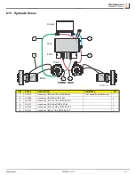
Hydraulic Hoses

5

Maintenance

WZ1000 6/5/23

5-5

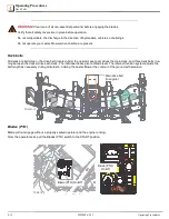
5.15 Hydraulic Hoses  

REF

PART #

DESCRIPTION

COMMENTS

QTY

1

106133

Hose Assy, 1/2LPx20-1/2In ORFS 8 45-45

Color coded for illustration only

1

2

105986

Hose Assy, 1/2HPx32in ORFS 8 ST

4

3

106129

Hose Assy, 1/2LPx10-1/2In ORFS 8 ST-ST

1

4

106131

Hose Assy, 1/2LPx24In ORFS 8 ST-45

1

5

106135

Hose Assy, 1/2LPx14-3/8In ORFS 8 ST-45

1

6

106137

Hose Assy, 1/2LPx7-1/2In ORFS 8 ST-ST

1

TDWZ1-21

1

2

3

4

5

6

FRONT VIEW

Cooler

Filter

Tank

Pump

Motor

Summary of Contents for WZ1000 Series

Page 1: ...WARNING Read and understand this manual before using this machine The Articulator Owner s Manual WZ1000 series D4920 Manual number MWZ1000D4920 Beginning serial number 72041121...

Page 2: ...ianapolis IN 46214 Phone 317 892 4444 800 515 6798 www lastec com DOLIRUQLD 3URSRVLWLRQ DUQLQJ 51 1 UHDWKLQJ JDV GLHVHO HQJLQH H KDXVW H SRVHV RX WR FKHPLFDOV NQRZQ WR WKH 6WDWH RI DOLIRUQLD WR FDXVH...

Page 3: ...y Rules 2 4 2 9 Use Caution When Working With Batteries 2 5 2 10 Safe Booster Cable Operation 2 5 2 11 Safety Decals and Symbols 2 6 2 12 Hazard Identified Chart 2 7 SECTION 3 INITIAL SET UP 3 1 3 1 P...

Page 4: ...Mower 4 13 SECTION 5 MAINTENANCE 5 1 5 1 Maintenance 5 1 5 2 Every 8 Operating Hours or Daily 5 1 5 3 First 25 Operating Hours 5 1 5 4 First 50 Operating Hours 5 1 5 5 Every 50 Operating Hours 5 1 5 6...

Page 5: ...Lastec Mower in the spaces provided below Model Number ______________________________ Serial Number ______________________________ These numbers can be found on the serial number plate decal which is...

Page 6: ...her warranty from warrantor Warrantor agrees to warranty for a period of ninety 90 days from date of purchase to any original purchaser who is a rental yard lease based business or temporary use facil...

Page 7: ...ed RIGHTS OF PURCHASER The validity and effect of this limited warranty as well as its interpretation operation and effect shall be determined exclusively by the principles of law and equity of the St...

Page 8: ...the top of the deck The purpose of this manual is to assist you in properly and safely operating and maintaining the mower Read and understand this entire manual before attempting to set up operate a...

Page 9: ...onal Safety Rules WARNING Do not allow non essential personnel especially children on or near the mower Do not operate the mower when non essential personnel especially children are present Clear area...

Page 10: ...e near the mower while operating Do not allow anyone near or in the path of discharge Do not discharge in the direction of bystanders vehicles or buildings Do not stop or start suddenly when going up...

Page 11: ...ersonal Protection Equipment such as eye hand head and ear protection when performing any service or maintenance to the drive unit or deck Keep the drive unit engine area free of accumulated debris fu...

Page 12: ...right side of the engine bay 5 Connect other end of positive cable to positive terminal of assisting battery 6 Connect negative cable to negative terminal of assisting battery WARNING Make final conn...

Page 13: ...and heed the warnings where they appear on your Lastec Mower Attention Caution Rotating Blades Pinching Crushing Danger Keep Hands and Feet Away from Blades Keep Covers Locked Down Pinch Point Read th...

Page 14: ...rds around belts and pulleys Clear warning in manual Battery explosion Improper battery handling or jumping Instructions on battery handling from the Bat tery Council International included in manu al...

Page 15: ...uel tanks located at the left and right side fenders which are shipped dry no fuel from the factory Fuel the Lastec Mower before operating The engine has been run at the factory so bleeding the fuel l...

Page 16: ...e Oil WARNING Turn off engine before checking the oil level changing the oil or chang ing the oil filter Allow ample time for oil to cool before changing or repairing leaks CAUTION Check the engine oi...

Page 17: ...k the coolant while the engine is running or hot Allow ample time for coolant to cool before checking changing or repairing leaks CAUTION Clean radiator daily Overheating may occur if radiator is not...

Page 18: ...o operation If the coolant appears excessively contaminated or diluted change the coolant prior to operation 4 Check the entire coolant system for any leaks Radiator Overflow tank Hoses Clamps Fitting...

Page 19: ...ay occur 3 Check the entire hydraulic system for any leaks Motors and pumps Filter Tank All hoses clamps and fittings and Entire area under the hydraulic system 4 Repair or replace the defective parts...

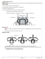
Page 20: ...re tight 6 Remove the unit from the jack stands 3 10 Hydrostatic Pump Belt WARNING Do not inspect adjust or change the hydrostatic pump belt while the engine is running The hydrostatic pump drive belt...

Page 21: ...pro jectile hazards The pulley idler belt tensioning system located on decks 1 3 and 5 automatically tensions the belts on the mower decks thus eliminating the need for manual belt tension adjustment...

Page 22: ...seat pan is properly latched and operator seat is secure 2 Ensure the seatbelt is secure and operable 3 Adjust the seat forward or back so that the operator can easily reach the control panel steering...

Page 23: ...e any deck changes before operating the mower All adjustment points must be set to the same height Center deck 1 Push the deck height control foot lever outward or use the adjustment tool stored next...

Page 24: ...area the deck will be set at 1 height of cut 1 Remove the top retaining pin 2 Remove the top washer 3 Allow the caster assembly to slide down approximately 1 2 inch 4 Reposition spacers as needed a Sp...

Page 25: ...quire frequent adjustment However fine adjustment is avail able if warranted 1 Loosen do not remove the yoke mounting bolts 2 Loosen the jam nut on the adjustment bolt 3 Set the adjustment bolt tot th...

Page 26: ...of the blades 1 Loosen the jam nut near the front of the link tube counter clockwise turn 2 Use a 5 8 open end wrench on the flats of the linking rod 3 Rotate the link rod clockwise to raise the back...

Page 27: ...e measuring technique on deck 2 and 4 use the rear wheel adjust ment rod see Rake adjustment in 3 16 to achieve desired rake 9 Decks 1 and 5 require no calibration 3 18 Discharge Configuration WZ1000...

Page 28: ...s 3 19 Tires and Wheels 1 Check the air pressure in the rear drive tires 2 Maintain air pressure at 18 psi or as needed to maintain level deck cutting 3 Verify proper function of all mower deck wheels...

Page 29: ...the following equipment inspection prior to each operation of the Lastec Mower Verify that the parking brake is set Check the fuel level Check engine oil level and condition Check the air cleaner and...

Page 30: ...scharge chute is clear of debris properly mounted and in good condition Inspect entire Lastec Mower for loose or entangled parts debris obstructions or neglected tools Check engine for abnormal exhaus...

Page 31: ...5 Avoid starting and stopping on slopes Avoid making sudden changes in speed or direction Make turns slowly and gradually Disengage the blades when crossing gravel drives walks or roads and while not...

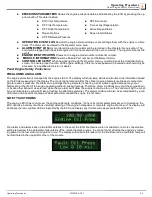
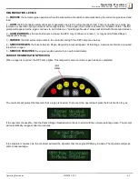
Page 32: ...l position while engine is running cranks engine to start NOTE When the key switch is in the RUN position The Controller will power up so the operator may check hours voltage coolant temp fuel level e...

Page 33: ...will still not start discontinue the starting process until the cause of malfunction is determined 2 Release immediately when the engine starts NOTE The key switch returns to the RUN position 3 Adjus...

Page 34: ...eventually wrap around to the beginning of the operator menu structure 5 Press the Menu key at any time while in a topic will return you to the main menu topic heading 6 Press the Menu and Enter keys...

Page 35: ...arnings that a parameter is nearing a point where engine damage may occur Alarms are at the limit of the engine operating without causing damage Therefore alarm conditions may shut the engine down or...

Page 36: ...ined by entering the Emissions Parameters menu described above The regen status can be set to two different states Auto or Regen Inhibit When the unit is in Regen Inhibit the ECU will not be able to i...

Page 37: ...nd a Parked Regen request DPF Lamp 3 PARKED the ECU will send prompts to the controller and light the DPF Lamp see below 4 SERVICE REGEN the Kubota Service Regen Required prompt will appear At this st...

Page 38: ...Enter key To ensure that the engine load is removed the regen process requires that the parking brake input Pin B5 closed to ground and the Neutral Switch Pin B2 closed to ground are applied It is not...

Page 39: ...astec Mower is equipped with a dedicated hydrostatic pumps for each rear drive wheel These pumps are controlled sep arately with each of the steering control levers located to the left and right of th...

Page 40: ...rom the neutral lock Steering levers NOTICE In all cases the further from neutral a steering lever is pushed pulled the faster the travel for that drive wheel Avoid pivoting on one wheel Turf damage m...

Page 41: ...rought in sandy soil areas or when performing seasonal scalping When conditions like this are evident lift created by the cutter blades can be reduced decreasing the abrasion wear to the cutter blades...

Page 42: ...driven the drive belt located under the operator seat pan drives the main deck and three deck belts run ning between the decks drive each deck The individual decks pivot at blade level The idler belt...

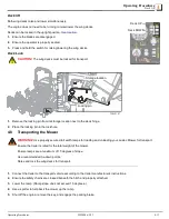
Page 43: ...the lock hole 4 8 Transporting the Mower WARNING Use properly secured full width ramps for loading and unloading your Lastec Mower for transport Ensure the trailer is rated for the total weight of th...

Page 44: ...ng the Mower 4 4 14 WZ1000 6 5 23 Operating Procedures 6 Tie down the machine between the front caster wheels and the rear bumper 7 Refer to local regulations for tie down requirements TDWZ1 26 TDWZ1...

Page 45: ...locating tabs and turn latches CW by a half turn with a 7 16 wrench or socket Verify the belt covers are securely fastened Grease all grease zerks Inspect the spindle bearing grease seals under each...

Page 46: ...tate tires 5 11 Bi Annual Replace fuel lines and clamps 1 Replace radiator hoses and clamps 1 Replace battery 5 12 Urethane Bushings CAUTION Bolts holding urethane bushings must remain tight Failure t...

Page 47: ...GLWLRQ 9HULI SURSHU LQVWDOODWLRQ RSHUDWLRQ DQG IORZ RI JUDVV FKXWH QVSHFW HQWLUH DVWHF 0RZHU IRU ORRVH RU HQWDQJOHG SDUWV GHEULV REVWUXFWLRQV QHJOHFWHG WRROV RU RWKHU KD DUGV KDQJH GUDXOLF RLO DQG ILO...

Page 48: ...enance Lubrication Points 5 5 4 WZ1000 6 5 23 Maintenance 5 14 Lubrication Points Lubricate every 8 hours of operation TDWZ1 20 Hydraulic idler Deck pivot collar Wheel yokes Mule drive belt idler TDWZ...

Page 49: ...In ORFS 8 45 45 Color coded for illustration only 1 2 105986 Hose Assy 1 2HPx32in ORFS 8 ST 4 3 106129 Hose Assy 1 2LPx10 1 2In ORFS 8 ST ST 1 4 106131 Hose Assy 1 2LPx24In ORFS 8 ST 45 1 5 106135 Hos...

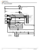
Page 50: ...Crank Signal D CANBus High CANBus Low Battery Negative B V U E B Junction Terminals 2 BLK RED 34 CR1 85 86 6 1 CANBus Low Digital Input 1 Fuel Level Input CTRL MOD B CTRL MOD B 26 25 24 23 21 2 2 2 2...

Page 51: ...A 3 Clutch 5 2 2 CR3 30 87 4 5 Con nues from page 1 Seat 41 CR3 87A 30 9 F3 2A 8 S4 2 1 3 FWD BAT BAT T1 T2 SOL1 Left Wing Actu ator Right Wing Actuator S9 REV 10 11 12 13 14 13 12 Actuator Switch Sea...

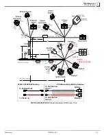
Page 52: ...B 12C 12A 13C 13A 10B 11B 2P 23B 1D 2KK 2C 2SS 2W 2CC 1A 1C Splice1 Splice2 Splice4 Splice5 5 0 1 2 0 1 2 CB1 10 1B 21F 3A 2M 32B 34A 21T 2R 5A 4B 8A 38D 2T 35D 39A 36A 39M 2DD 18B 19A 20B 3F 4A 8B 9A...

Page 53: ...000 6 5 23 5 9 Battery Battery To Distribution Stud To Distribution Stud To Engine Block To Starter 073698 Auxillary Battery Harness 073814 073815 Wire Assy WZ1000 WZ800 WZ600 Chassis Harness 122130 r...

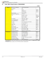
Page 54: ...22022 Main Drive Belt Belt C142 Mule Drive 072698 Deck Drive Belts Center Belt 72 Deck Drive 048272 Wing Deck Right Belt Insta Power 85890 P706 Wing Deck Left Belt Insta Power 85950 063879 Maximum For...

Page 55: ...PM Compression Ratio 18 1 Dry Weight 432 lbs Oil API Service Class SC or SH SAE 10W 30 Oil Capacity w Filter Approx 7 4 US qt 7 0L Oil Filter Filter 122204 Fuel Diesel Fuel No 2 D ASTM D975 Fuel Capac...

Reviews: