background image


Install the CT74 Clock  

  3 

Step 3:

 The CT74 clock communicates with PayClock Online using a 

Wired Network Connection. Plug the wired network cable into the 
Ethernet port and the Power Adapter plug into the power adapter port 
located in the compartment on the back of the clock.


Step 4:

 Align the CT clock with the tabs on the mounting-plate and 

secure the two together with the 2 Philips head screws. Be careful not to 
pinch the AC cord or network cable. 


When finished, plug the power adapter into an AC wall outlet. 

Summary of Contents for CT SERIES

Page 1: ...CT Series Terminal User s Guide Model CT74...

Page 2: ...ice must accept any interference received including interference that may cause undesired operation WARNING Changes or modifications to this product not expressly approved by the party responsible for...

Page 3: ...nrolling Faces 13 Administrator Functions 15 Troubleshooting the CT74 20 Appendix A Enrollment Guide 22 Appendix B Testing the Connection to PCO 24 Appendix C Using the Select Transaction Screen in Au...

Page 4: ......

Page 5: ...ab in the upper right corner after the clock is installed Recommended Installation Tools Online and Email Support Lathem com provides access to numerous support resources Visit the following link http...

Page 6: ...ng the registration process Step 2 After selecting the appropriate installation site use the clock to determine the appropriate height Have the shortest employee stand in front of the clock Hold the c...

Page 7: ...thernet port and the Power Adapter plug into the power adapter port located in the compartment on the back of the clock Step 4 Align the CT clock with the tabs on the mounting plate and secure the two...

Page 8: ...cks from the list of items on the left Click New The Select Clock Type window will open Choose CT74 and click Select The clock properties will display From the General tab enter a name for the clock u...

Page 9: ...lock Online After the connection is made the data will be downloaded to the clock and it will be ready for use When complete a cloud icon will show on the clock s display identifying it is connected t...

Page 10: ...y record a punch for the employee and not display the Select Transaction screen Employee Transactions Employees can record transactions or view total information by presenting their face a badge or en...

Page 11: ...utton the clock will go to the PIN entry screen Tap the Scan Face button the clock will validate the face At the Select Transaction screen tap the Amounts button Using the numeric key pad enter the va...

Page 12: ...nfirmation will sound and the Select Transaction screen will display Tap a button to select your transaction or wait for the 2 second timer to elapse and a punch will be recorded A confirmation will s...

Page 13: ...reen will display showing the department into which the employee transferred Amount Entries Present an enrolled face in front of the clock At the Select Transaction screen tap the Amounts button Using...

Page 14: ...will display Use one of the following methods to enter Supervisor Mode Tap Scan Face and present an enrolled face in front of the clock Using the numeric key pad enter the supervisors PIN and tap OK M...

Page 15: ...ed punch will display on the screen and will be added to the employee s timecard When finished tap to return to the default screen Viewing Totals Tap the SUPERVISOR button on the clock The IDENTIFICAT...

Page 16: ...ext message When finished tap to return to the default screen Override Lockout Tap the SUPERVISOR button on the clock The IDENTIFICATION screen will display Using either a face badge or PIN enter supe...

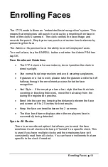
Page 17: ...lasses or a hat is worn please take the glasses and or hat off halfway through the enrollment process for better face recognition Hair Style If the employee has a hair style that has their hair coveri...

Page 18: ...face back Turn the head to the right and then to the left Raise the head up slightly and then lower the head down slightly Continue moving face as described above The progress bar at the bottom of sc...

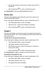
Page 19: ...ill display Network This menu allows you to configure the network communication settings between the clock and PayClock Online At the clock tap the Settings button and enter the administrator PIN The...

Page 20: ...p Date Time and make the desired changes When finished tap to return to the default screen Signal Door Access This menu allows you to configure how the clock uses the on board relay At the clock tap t...

Page 21: ...menu item allows you to test the clocks connection to the internet and PayClock Online You can also display any errors that the clock may have experienced Testing the Clocks Internet Connection At the...

Page 22: ...nufacturer default settings All settings administrators supervisors employees and data will be cleared from the clock you cannot recover this information At the clock tap the Settings button and enter...

Page 23: ...ck in the box means the option is selected When finished tap to return to the default screen Note The Select Transaction screen can still be accessed by an employee if needed See Appendix C for detail...

Page 24: ...powered up If after going through each item above you are still not communicating have the network administrator or IT person make sure there aren t any issues with the network CT74 Troubleshooting I...

Page 25: ...not paper Avoid using water or cleaners Why is the CT74 not reading the employee s face when enrolling or punching If the employee s facial appearance has changed re enroll the employee Make sure the...

Page 26: ...ps below Position yourself and bend at the waist to bring your face 1 2 5 ft from the screen on the clock The line of dots at the bottom of the screen indicate how much data is needed to complete the...

Page 27: ...eyes centered on the screen Tilt the head down slightly chin lowered while keeping your eyes on the screen then tilt the head back slightly chin upward If you wear glasses all of the time or on occasi...

Page 28: ...est will verify the internet connection access to the internet through the required ports and the connection to the PayClock Online service With the clock powered up and connected to the network tap t...

Page 29: ...he test Fail What should I do if this test fails Open the listed port s to Inbound Outbound traffic Contact your IT department to open the listed port s to traffic Notes The internet test will attempt...

Page 30: ...employee if needed by following these steps Present face the clock will start scanning Tap the Stop Scan button the clock will go to the PIN entry screen Tap the Scan Face button the clock will valida...

Page 31: ...lly Open COM Common NC Normally Closed Bell Relay Connections When you are connecting to a signaling device make sure you have the following skills Understand basic wiring principles and techniques Ca...

Page 32: ...ire splices should be done externally See the following diagrams for details Important Relay contacts provide no power for signaling devices The relay is a dry contact closure rated 2 amps at 24VDC or...

Page 33: ...Appendix D Bell Relay Connections 29...

Page 34: ...30 Appendix D Bell Relay Connections...

Page 35: ...31 Wiring to P A System Tone Generator Important Connecting the CT clock to a public address PA system requires the use of an external Tone Generator Contact your PA supplier to acquire an appropriat...

Page 36: ...clock Connect the wires from the door access device to the screw terminals Plug the terminal connector into the socket on the CT clock Only one 1 wire should be inserted into the terminal block positi...

Page 37: ...Appendix E Access Relay Connections 33 Wiring for a Door Access Control System Door Strike Wiring For Door Strikes more than 1 5 Amps Peak...

Page 38: ...l Events The Signal Event Schedule screen will display Tap add event The Add Event screen will display Using the up and down arrow keys select the desired hour minute and AM PM for the bell event Tap...

Page 39: ...urn to the default screen Deleting a Bell Event From the CT tap Settings and enter the administrator PIN and tap OK From the Administrator Main Menu tap Signal Door Access The Signal Door Access scree...

Page 40: ...e product must be shipped in its original carton or equivalent fully insured with shipping charges prepaid Lathem will not assume any responsibility for any loss or damage incurred in shipping 6 WARRA...

Page 41: ......

Page 42: ......

Page 43: ......

Page 44: ...USG0104...

Reviews: