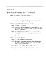
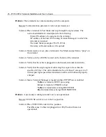
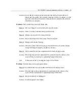
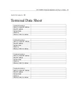
background image

PC3500TX Terminal Installation & User’s Guide - 23 


A

P P E N D I X  

C  

Network Wiring Topologies 


Typical Lan network configuration 


PC running Terminal Manager 
TCP/IP Server 

Network Switch 

Summary of Contents for PC3500TX

Page 1: ...PC3500TX Terminal Installation User s Guide...

Page 2: ...es prepaid Lathem will not assume any responsibility for any loss or damage incurred in shipping 6 WARRANTY DISCLAIMER AND LIMITATION OF LIABILITY Except only the limited express warranty set forth ab...

Page 3: ...d to comply with the limits for a Class A digital device pursuant to Part 15 of the FCC Rules These limits are designed to provide reasonable protection against harmful interference when the equipment...

Page 4: ...15 To Test the Badge Reader 15 Battery Test 16 DI DO Test 16 Restart Mode 17 UNLOCKING YOUR TERMINAL THROUGH TERMINAL MANAGER 17 USE THE TERMINAL 18 To punch 18 To transfer 19 To start a New Day 19 To...

Page 5: ...k lit super twist LCD Terminal 12 or 24 hour format USA or International quartz precision Time Stamp on data transactions Indicators LED s indicate low Power yellow Invalid registration red and Valid...

Page 6: ...oximate Power Surges and Spikes Any time your terminal is connected to AC current a power surge or spike can occur You should use high quality surge suppressers to protect your PC3500TX The warranty d...

Page 7: ...that is used to note specific information about the terminal This information should be written on the sticker and placed on either side or the bottom of the terminal This will be used when the termin...

Page 8: ...rom the floor and tape the template into place Drill the 3 holes noted on the template using a 5 16 drill bit If wires will be routed through the wall drill up to a 3 4 hole as indicated on the templa...

Page 9: ...ion cable and 12VDC power pack cable to the terminal Insert the key into the mounting bracket lock and turn the key counter clockwise Align the slots on the back of the terminal with the tabs on the t...

Page 10: ...plug is attached to the cable unlock and remove the terminal from the mounting bracket Route the cable through the desired knockout of the mounting plate and plug the RJ45 plug into the Ethernet Commu...

Page 11: ...de IMPORTANT The PC3500TX terminal requires that the Terminal Manager module runs with TCP IP Server enabled The available tests and setup modes are Test Mode Tests the Keypad Display Memory Real Time...

Page 12: ...switch to the USE position toward the modular jacks Plug the terminal 12VDC power supply into the power connector The terminal goes through the power up test beeps and the lights flash The display me...

Page 13: ...ine of the display Press the ENTER key three 3 times to clear all memory prior to setting up the terminal After resetting the terminal will again display TEST MODE NOTE Skipping this step greatly incr...

Page 14: ...at is running the Terminal Manager Module unique IP address See your network administrator for assignment Enter the host s numeric IP address in blocks of three followed by the ENTER key Once all four...

Page 15: ...he XXXXXXXXXXXX represents the unique Ethernet address programmed into the EPROM by the factory Also known as the MAC Address Important Write this number down on the Terminal Data Sheet and on the Ter...

Page 16: ...MODE message in the terminal display press the CLEAR key five 5 times The message RESTART MODE appears on the top line of the display Press the ENTER key three 3 times to clear all memory prior to se...

Page 17: ...must be a Static IP address that will be assigned by the network administrator Enter the terminal s numeric IP address followed by the ENTER key The following message will be displayed Enter Host IP T...

Page 18: ...for assignment Enter the numeric Subnet Mask address followed by the ENTER key The following message will be displayed Enter Keepalive Mode Press the CLEAR key and select Normal and press the ENTER ke...

Page 19: ...XXX Press the Enter key to go into Test Mode TEST MODE 128 YY The terminal displays TEST MODE on the top line followed by two sets of numbers The first number shows the amount of memory installed in k...

Page 20: ...ed the test will fail Press Clear to go to the DI DO Test DI DO Test If you have installed a bell relay you can use the DI DO Test to check the terminal s DATA IN DATA OUT port where the relay connect...

Page 21: ...letes the test and setup To exit the Test Mode place the TEST USE switch to the USE position and press the CLEAR key The terminal will goes through its power up sequence The terminal displays TERMINAL...

Page 22: ...n They can do this by swiping their badge or entering their badge number at the keypad To punch The PC3500TX series terminals have a bar code badge reader The bar code should be on the right side of t...

Page 23: ...nter To start a New Day Press New Day Swipe your badge or enter your badge number Note This function key must be enabled in the Advanced tab of the Terminal Properties To enter amounts Press Amount Sw...

Page 24: ...tal Hours if there is no Out punch for the day or Grand Total Hours when there is an Out punch for the day If you make a mistake pressing Clear removes your entry one digit at a time Supervisor Functi...

Page 25: ...de Remove the phillips head screw from the battery holder located in the mounting plate Remove the old battery Place the new battery into the battery compartment Replace the battery holder Plug the ba...

Page 26: ...details on connecting your signal devices Connect the relay module to the RJ 11 DI DO connector on the back of the terminal and place the terminal on the mounting bracket NOTE You must use an external...

Page 27: ...PC3500TX Terminal Installation User s Guide 23 A P P E N D I X C Network Wiring Topologies Typical Lan network configuration PC running Terminal Manager TCP IP Server Network Switch...

Page 28: ...24 PC3500TX Terminal Installation User s Guide Typical Wan network configuration PC running Terminal Manager TCP IP Server Network Router Network Switch Network Router...

Page 29: ...the outlet by plugging in another appliance NOTE The terminal will operate for about 4 hours with the optional battery backup after losing the primary voltage source Then the terminal will power off T...

Page 30: ...ity of LEDs located on the bottom of the terminal Solution Verify that the cable is plugged into both ends terminal and switch Solution Verify that the single segment cable length is equal or less tha...

Page 31: ...d Reason Badge reader needs cleaning Solution Moisten a clean cloth with isopropyl alcohol and wrap it around a badge Swipe this badge through the reader several times Reason The terminal has not been...

Page 32: ...ction key F2 has not been enabled in the Terminal Manager software Solution Open the PC3500TX s Terminal Properties in Terminal Manager Select the Advanced tab Check the Allow Start New Day Registrati...

Page 33: ...Subnet Mask Gateway Ethernet MAC Address Terminal Location Static Terminal IP Address Host IP Address Subnet Mask Gateway Ethernet MAC Address Terminal Location Static Terminal IP Address Host IP Addr...

Reviews: