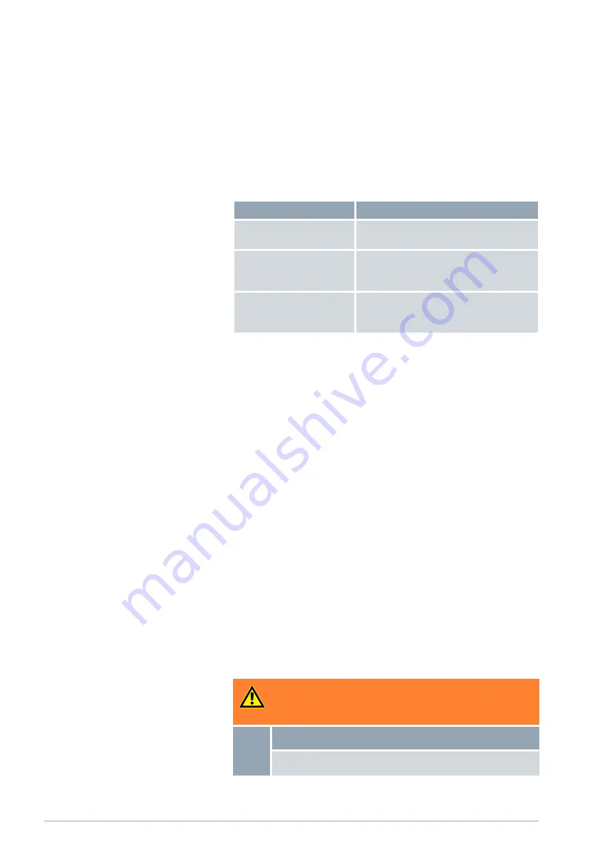
All water-cooled devices are equipped with the following cooling water con-
nection:
n
Exterior thread (male) G ¾ inch
Table 7: Cooling water data
Specification
Value
Maximum cooling water
pressure
10 bar
Cooling water temperature
15°C recommended; 10 to 30°C permitted
(in upper temperature range with reduced
cooling output)
Cooling water pressure dif-
ference Fig. 91
3 bar recommended; 0.8 to 5 (10) bar
permitted (in lower temperature range with
reduced cooling output)
Please note:
n
Connect the cooling water inlet and outlet according to the labeling on
the device. The inlet and outlet of the cooling water supply may not be
interchanged.
n
The hoses used for the cooling water circuit must be suitable for the
temperature range specified. Also observe the permitted hose diameter.
n
Secure the hose nozzles or the coupling connectors to the hoses using
hose clips.
n
Secure the water cooling return hose in the outlet area to prevent the
hose from jerking suddenly, even when pressure surges occur.
Secure the water cooling return hose in the outlet area in such a way
that hot cooling water cannot spray out.
n
Avoid kinking or crushing the hoses.
n
We recommend using a leakage water detector with water shut-off
function to prevent leakages from causing damage in the cooling water
system.
n
Only use cooling water that meets the quality requirements.
n
If the condenser leaks, there is a danger that refrigerating machine oil or
combustible/non-combustible refrigerant from the device’s refrigerant
circuit will mix with the cooling water. Observe the legal requirements
and provisions of the water supply company applicable at the operation
site.
4.7 Configuring interfaces
WARNING!
Touching pieces charged with voltage when installing the mod-
ules
Electric shock
Disconnect the device before installing modules.
Personnel:
n
Specialized personnel
V6
Integral Process Thermostats and High-Temperature Thermostats
44 / 198


