Idle state
n
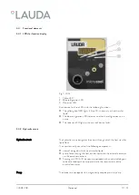
The alarm output is in resting state:
When the device is switched off,
after switching on if a fault is already evident at that time (e.g. level
too low)
and during normal operations when a fault occurs.
n
Pins 1 and 2 are open.
n
Pins 3 and 2 are closed.
GO state
n
The alarm output is in a sound state when no faults occur.
n
Pins 1 and 2 are closed.
n
Pins 3 and 2 are open.
Information on the settings for the alarm output can be found in
Chapter 6.8 ‘Configuring alarm output’ on page 44
.
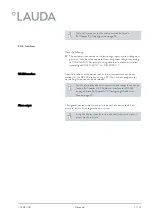
Note the following:
n
The equipment connected to the low voltage inputs and low voltage out-
puts must have be safely separated from dangerous voltages according
to DIN EN 61140. For example, using double or reinforced insulation
according to DIN EN 60730-1 or DIN 60950-1.
n
Only use shielded connection cables. Connect shield to connector case.
Cover unused plug connections with protective caps.
V05REV08
Microcool
28 / 57
Summary of Contents for MC 250
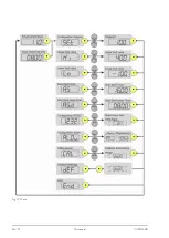
Page 36: ...Fig 12 Menu V05REV08 Microcool 36 57...
Page 58: ......
Page 60: ......
Page 62: ......
Page 63: ......


