background image

Data

Value Unit

Transport temperature range

-20 ... 60 °C


Operating temperature

range

Dimensions (W x D x H)

Weight


°C

mm

kg

MC 250

-10 ... 40

200 x 350 x 465

26

MC 600

-10 ... 40

350 x 480 x 595

51

MC 1200

-10 ... 40

450 x 550 x 650

64

MC 1200 W

-10 ... 40

450 x 550 x 650

64

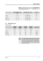
11.2 


Refrigeration unit


Cooling capacity


Cooling

capacity

(20 °C)

Cooling

capacity

(10 °C)

Cooling

capacity

(0 °C)

Cooling

capacity

(-10 °C)

Refrigerant


kW

kW

kW

kW


MC 250

0.23

0.2

0.15

0.09

R134a

MC 600

0.6

0.5

0.36

0.15

R134a

MC 1200

1.15

1.05

0.75

0.4

R134a

MC 1200 W

1.15

1.05

0.75

0.4

R134a

The cooling capacity is measured for a specified tem

per

-

ature of the 

heat transfer liquid

. Information is provided 

in b

rackets. The ambient temperature for the measure-

ment is 20 °C; ethanol was used as heat transfer liquid.

The cooling water temperature is 15 °C and the cooling

water differential pressure is 3 bar for the measurement

of water-cooled devices.

Technical data

Microcool


61

Summary of Contents for MC 250

Page 1: ...Operating instructions The right temperature worldwide Microcool MC 250 MC 600 MC 1200 MC 1200 W Circulation chiller...

Page 2: ...ting instructions LAUDA DR R WOBSER GMBH CO KG Postfach 1251 97922 Lauda K nigshofen Germany Phone 49 0 9343 503 0 Fax 49 0 9343 503 222 E Mail info lauda de Internet www lauda de YAWE0033 V02REV60 10...

Page 3: ...ypes 12 3 2 Design of the circulation chiller 13 3 3 Controls 17 3 3 1 Mains power switch 17 3 3 2 Display buttons 18 3 4 Function elements 19 3 4 1 LEDs for function display 19 3 4 2 Hydraulic circui...

Page 4: ...5 Restricting temperature limit values 41 6 6 Configuring timer 42 6 7 RS232 interface 44 6 7 1 Configuring RS232 interface 44 6 7 2 Protocol 45 6 7 3 Write commands 46 6 7 4 Read commands 46 6 7 5 Er...

Page 5: ...osing of refrigerant 59 10 2 Device disposal 59 10 3 Disposing of packaging 59 11 Technical data 60 11 1 General data 60 11 2 Refrigeration unit 61 11 3 Hydraulic circuit 62 11 4 Voltage dependent dat...

Page 6: ...ards are reduced using any of the following measures If relevant there are safety devices for the device These devices are essential for the safety of the device Their func tionality must be ensured w...

Page 7: ...cement of the device on a tabletop surface only permitted for MC 600 and MC 1200 W Setting an incorrect pump pressure 1 4 Modifications to the device Any technical modifications to the machine are pro...

Page 8: ...transfer liquid are made of high quality materials suitable for the operating temperature Stainless steel and temperature resistant plastics are used 1 7 Hoses Only LAUDA hoses are permitted to be us...

Page 9: ...certain activities These protec tive goggles must comply with the legal requirements for personal protective equipment of the European Union 1 11 Structure of safety instructions A safety instruction...

Page 10: ...le injuries if the safety instruction is disregarded CAUTION Type and source Consequences in the case of non compliance Measure 1 Measure A notice warns about possible property or environmental damage...

Page 11: ...ly after delivery for completeness and transport damage If there is unexpected damage to the device or accessories inform the carrier immediately so that a damage report is produced and a check of the...

Page 12: ...Air cooled tabletop device with a cooling capacity of 250 watts MC 600 Air cooled floor standing device with a cooling capacity of 600 watts The pump pressure can be adjusted using a bypass adjustmen...

Page 13: ...side 1 Pump connection outlet 2 Overflow connection 3 Pump connection return 4 Rating plate 5 Drain plug 6 RS232 interface 7 Alarm output 8 Mains cable 9 Ventilation openings Rear side MC 250 Design...

Page 14: ...culation chiller Fig 1 Overview of the front side 1 Filler nozzle with cover 2 Level indicator 3 Control panel 4 Front panel with ventilation openings 5 Four support feet Front side MC 250 Design and...

Page 15: ...front side 1 Filler nozzle with cover 2 Control panel 3 Level indicator 4 Manometer 5 Front panel with ventilation openings 6 Four castors with locking brakes Front side MC 600 MC 1200 W Design and f...

Page 16: ...ction outlet 2 Bypass adjustment wheel 3 Pump connection return 4 Overflow connection 5 Rating plate 6 Drain plug 7 RS232 interface 8 Alarm output 9 Mains cable 10 Ventilation openings Rear side MC 60...

Page 17: ...ons 4 Mains power switch 3 3 Controls 3 3 1 Mains power switch The mains power switch can be put in the following positions In position I the device is switched on In position O the device is switched...

Page 18: ...on 3 DOWN arrow button Functions in the display of the device can be controlled using the display buttons A selection in the display can be confirmed with the ENTER button The UP and DOWN arrow button...

Page 19: ...ts in the event of device faults 3 4 2 Hydraulic circuit The hydraulic circuit designates the circuit through which the heat transfer liquid flows The circuit basically consists of the following compo...

Page 20: ...is regulated using the bypass adjustment wheel on the rear side 3 4 4 Level indicator The fill level of the heat transfer liquid in the circuit can be read using the level indicator The top arrow indi...

Page 21: ...ion for the refrigeration unit can be found in on page 61 3 4 6 Interfaces Note the following The equipment connected to the low voltage inputs and out puts must have safe separation from dangerous vo...

Page 22: ...n the refrigerant low pressure side expansion evaporation Voltage Device must only be connected to this voltage and frequency Power consumption Power consumption of the device during operation Protect...

Page 23: ...been tested and found to comply with the limits for Class A digital device pursuant to Part 15 of the FCC Federal Communication Commission Rules These limits are designed to provide reasonable protec...

Page 24: ...can be found in Chapter 4 1 EMC classification on page 23 WARNING Rolling away falling over of the device Impact crushing Do not tilt the device Place the device on a level non slip surface with suff...

Page 25: ...formation about the pump connections of the individual devices can be found in Chapter 11 3 Hydraulic circuit on page 62 Hoses not insulated Type Olive Application area Internal in mm External diamete...

Page 26: ...talogue number Max temperature in C Internal in mm External diameter in mm Suitable for hose RKJ 058 105 19 54 RKJ 112 RKJ 024 125 16 36 RKJ 112 RKJ 009 105 23 43 RKJ 031 RKJ 013 125 29 50 RKJ 032 Ada...

Page 27: ...ll a tem perature drop between device and external consumer occurs due to flow rate too low In this case increase or lower the tem perature accordingly Secure the temperature control hoses with hose c...

Page 28: ...g water circuit Water containing iron and iron particles in the water result in rust formation in the cooling water circuit Hard water is not suitable for cooling due to the high lime con tent and res...

Page 29: ...he sink area to prevent uncontrolled sliding also in the event of pres sure surges Fix the supply hose of the water cooling in place in the sink area so that spraying out of hot cooling water is not p...

Page 30: ...he PC using a straight through cable Without hardware handshake Set the corresponding operating mode on the PC Use shielded connection cables Connect shield to connector case The cables must be galvan...

Page 31: ...s in GO state immediately after switching on and during normal operation without faults Pins 1 and 2 are closed Pins 3 and 2 are open Note the following The equipment connected to the low voltage inpu...

Page 32: ...temperature Container size Catalogue number 5 l 10 l 20 l Kryo 30 Mono eth ylene glycol water 30 90 4 50 at 25 C LZB 109 LZB 209 LZB 309 Aqua 90 decalcified water 5 90 1 LZB 120 LZB 220 LZB 320 Note t...

Page 33: ...ge of the application WARNING Overflow of heat transfer liquid Electric shock Ensure that the device is not overfilled Note the level indicator and the thermal volume expansion of the heat transfer li...

Page 34: ...e filler nozzle carefully Mon itor the level indicator Fill the device up to the maximum fill level If necessary use a funnel for the filling The level indicator must not be above the max imum fill le...

Page 35: ...it is active 2 Depending on the size of the consumer heat transfer liquid must be refilled if necessary Monitor the level indicator for this Further information about refilling heat transfer liquid ca...

Page 36: ...on itor the level indicator If necessary use a funnel for the filling The level indicator must not be above the max imum fill level The level indicator must be above the minimum level Otherwise a warn...

Page 37: ...pump use a safety valve for protection This safety valve must be installed in the outlet of the device 1 To reduce the pump pressure turn the bypass adjustment wheel anticlockwise until the maximum p...

Page 38: ...at transfer liquid can be found in Chapter 5 5 Refilling heat transfer liquid on page 35 6 2 Default display and menu items 1 Press the ENTER button to reach the menu items from the default display of...

Page 39: ...Fig 12 Menu Operation Microcool 39...

Page 40: ...rature range of your application i e in which range any temperature control can take place A warning is output by the device if the temperature is outside the limits This range is necessary so that no...

Page 41: ...ettings of 45 0 C and 5 0 C stored in the device cannot be changed Practical temperature limit values are Aqua 90 Set the range to the values 42 C and 3 Kryo 30 water glycol Set the range to the value...

Page 42: ...the current actual tem perature on the display is shown with a flashing decimal point If Auto Shut Down is invoked using the corresponding menu item the remaining time for example 05 30 is shown flash...

Page 43: ...again afterwards after a specified time Otherwise you can start the device manually by pressing the ENTER button CAUTION Automatic device start using the auto start timer Frostbite risk of injury devi...

Page 44: ...n 1 Select the menu item for the Auto Shut Down or Auto Start 2 Input 00 00 3 Confirm with the ENTER button The value must be confirmed within 4 seconds after the last input Otherwise the screen retur...

Page 45: ...ing The interface operates with 1 stop bit no parity bit and 8 data bits Selectable transmission speed 2400 4800 9600 factory set ting or 19200 baud The RS232 interface can be operated with or without...

Page 46: ...racter is also permitted Response from the thermostat OK or ERR_X in the case of an error XXX XX XXX X XXX XXX XXX XX XXX X XXX XXX XX XX XX X XX XX XX XX XX X XX XX X XX X X X X X XX X X X X XX X XX...

Page 47: ...d decimal format XXX XX or XXX XX for neg ative values or ERR_X 6 7 5 Error messages The error messages of the modules are described in the following Error Description ERR_2 Incorrect input e g buffer...

Page 48: ...calibration If any temperature difference is discovered when checking the device with a reference thermometer the offset additive part of the characteristic curve of the internal measurement chain ca...

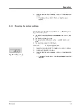
Page 49: ...ure limit values is reset to 45 C and 5 C The timers are reset to 00 00 The signal output at the alarm output is reset to alarms and faults The baud rate is reset to 9600 baud Personnel Operating pers...

Page 50: ...fer liquid are at room temperature before touching them NOTICE Contact with rotating part Severed parts of the body Repairs must only be performed by specialist per sonnel Also note the following Befo...

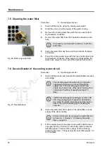
Page 51: ...r liquid 7 3 Cleaning the device Personnel Operating personnel WARNING Ingress of cleaning agents in the device Electric shock Use a moist cloth for cleaning Also note the following Only clean the con...

Page 52: ...dingly The descaling agent should be fed to the water cooling using a pump or a funnel through the supply hose The descaling agent return flow should be via flow hose of the water cooling into a conta...

Page 53: ...t thor oughly Allow at least 10 litres of water to flow through the device 7 7 Checking the heat transfer liquid Soiled or degenerated heat transfer liquid must be replaced Fur ther use of the heat tr...

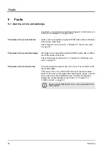
Page 54: ...warnings can be found in Chapter 8 3 Warnings over view on page 55 A two tone signal is output if any error occurs The red LED on the device also lights In the case of an error switch off the device...

Page 55: ...than 75 C 8 3 Warnings overview Warnings are not relevant for safety The device continues running A continuous tone is output for a short time by the device Warn ings are output periodically You are...

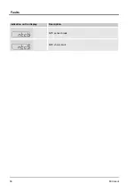
Page 56: ...Indication on the display Description NTC sensor break NTC short circuit Faults Microcool 56...

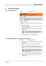
Page 57: ...from the device when the drain plug is opened 4 Open the drain plug Turn anticlockwise for this 9 2 Draining condenser only water cooled devices Personnel Operating personnel 1 Bring the device to ro...

Page 58: ...itching on the device blow compressed air through the supply nozzle into the device Continue blowing compressed air through the device until all the water has flowed out of the device Decommissioning...

Page 59: ...decommissioning is only permitted by a spe cialist Refrigerant GWP 100a R134a 1430 Global Warming Potential GWP time horizon 100 years according to IPCC IV 2007 Comparisons CO2 1 0 Type and fill quant...

Page 60: ...by up to 50 Ambient temperature range 5 40 C IP degree of protection IP 32 Contamination level 2 Clearance from surroundings front and rear sides 40 cm Overvoltage Overvoltage category II and transien...

Page 61: ...ling capacity 10 C Refrigerant kW kW kW kW MC 250 0 23 0 2 0 15 0 09 R134a MC 600 0 6 0 5 0 36 0 15 R134a MC 1200 1 15 1 05 0 75 0 4 R134a MC 1200 W 1 15 1 05 0 75 0 4 R134a The cooling capacity is me...

Page 62: ...16 mm 12 MC 1200 7 14 35 1 3 G 15 olive G Olive 16 mm 12 MC 1200 W 7 14 35 1 3 G 15 olive G Olive 16 mm 12 11 4 Voltage dependent data Power consumption MC 250 MC 600 MC 1200 MC 1200 W kW kW kW kW 23...

Page 63: ...bject to change 12 3 LAUDA contact Contact LAUDA Service Constant Temperature Equipment in the following cases In the event of faults on the device For technical questions about the device For spare p...

Page 64: ...ssure Equip ment Directive 97 23 EC as the device is classified in the area of Article 3 3 The requirements from the above mentioned Directives are thus sufficiently met for the pressure relevant haza...

Page 65: ...isposal refrigerant 59 Draining 57 Draining the condenser water cooled 57 Filling 33 Placement 24 Unpacking 11 Display buttons Operation 18 Disposal Packaging 59 Refrigerant 59 Disposing of refrigeran...

Page 66: ...flow hose 33 P Packaging Disposal 59 Personal protective equipment overview 9 Personnel qualification overview 8 Placement device 24 Placement location 24 Protective equipment personal overview 9 R Ra...

Page 67: ......

Page 68: ......

Page 69: ...il LAUDA voir plaque signal tique Typ Type Type Serien Nr Serial no No de s rie mit folgendem Medium betrieben wurde was used with the below mentioned media a t utilis avec le liquide suivant Dar ber...

Page 70: ......

Page 71: ......

Page 72: ...LAUDA DR R WOBSER GMBH CO KG Postfach 1251 97922 Lauda K nigshofen Germany Phone 49 0 9343 503 0 Fax 49 0 9343 503 222 E Mail info lauda de Internet www lauda de...

Reviews: