9
Note: The external controller display has no IP protection; make sure it is installed on a location protected
from the weather, from dust and from any water splashes.
If the chiller is controlled remotely, it is also possible to remove the display after the initial configuration and
store it in a safe location, as the chiller does not need it to operate. In such a case the end connector of the
display’s cable also needs to remain protected from the elements, for example keeping it inside the electrical
box of the chiller.
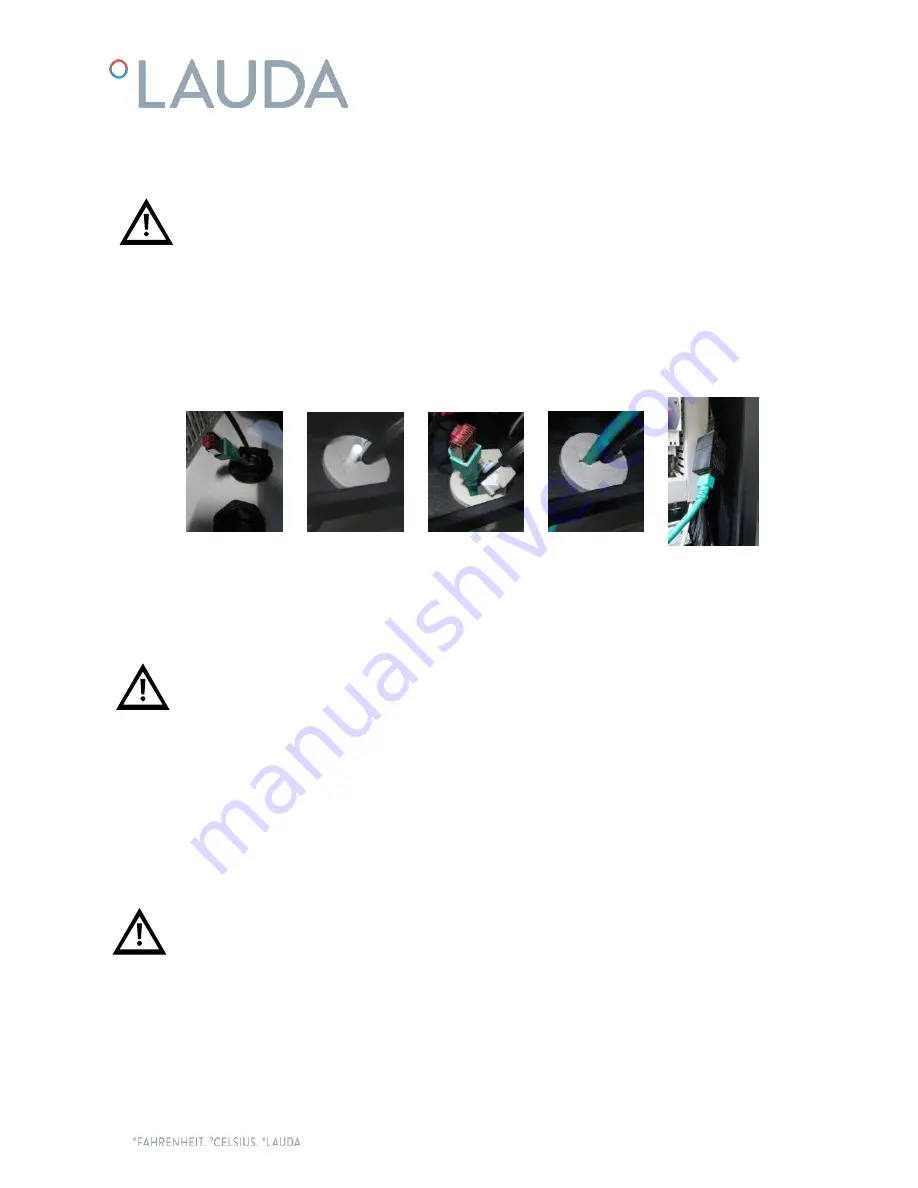
Ethernet cable connection, if the chiller is connected to a local network via Ethernet or to a Cloud gateway:
Introduce the Ethernet cable through the brush gland on the base of the chiller and into the electrical box
through the rubber cable holder, then connect it to the Ethernet connector on the right side of the electrical
box:
The chiller also has some special terminals prepared for the following functions (introduce the required cables
also through the brush gland on the base of the chiller):
Terminals 23 and 24, remote On/Off operation:
This chiller can be turned On and Off automatically by an
external signal. This remote On/Off signal is transmitted to these terminals by a dry contact in the application
(open contact = chiller Off, closed contact= chiller On).
Note: The chiller will not turn On unless these terminals are bridged. Once the commissioning operation is
complete, if the remote On/Off function described above is not used, connect the supplied wire bridge
between terminals 23 and 24 to be able to turn the chiller On from the display.
Terminals 25 and 26, external solenoid valve connection:
They can be used to supply a solenoid valve with
30VDC (the maximum power available for the solenoid valve is 25W). If the pipes of the application are
installed above the level of the chiller’s tank, this valve prevents backflow when the chiller is stopped. These
terminals are only at 30VDC when the water pump is working.
Terminals 57 and 61,
external alarm report signal:
These terminals provide a dry contact to report a general
alarm of the chiller. By default this contact closes when there is an active alarm. If necessary, an authorised
technical service can invert this logic so that the contact remains closed during normal operation and opens
when there is an alarm.
A system of fuses or circuit breakers must be installed before the power inlet connection to the Ultracool
unit. The maximum size of these protections is defined in the Ultracool characteristics plate.


