UWT circulation heat exchangers
29 June 2018 / 29/06/2018
Starting up
15
6
Starting up
6.1
Mains connection
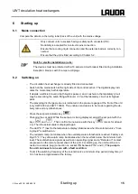
Compare the details on the rating label (back of the unit) with the mains voltage.
Only connect units to sockets having a safety earth conductor (PE).
No liability is accepted for incorrect mains connection.
Ensure that a cooling liquid connection and the external load are correctly con-
nected.
Ensure that the unit is filled according to Chapter 5.2.
Note for electric installation on site:
The devices must be protected with a 16 ampere circuit breaker fitted during installation.
Exception: Devices with 13 ampere UK plugs.
6.2
Switching on
The circulation heat exchanger is already filled and connected.
Switch on the mains switch at the right side of the control section. The digital display indi-
cates the momentary bath temperature.
If despite a sufficient level no bath liquid is passed, an air cushion in the laboratory circuit
may be preventing the pump filling with liquid.
Vent the laboratory circuit at its highest
point.
The prevailing discharge pressure is indicated on the pressure gauge at the front of the unit
(only UWT 6000 and UWT 10000). This enables conclusions to be made regarding the de-
livery rate and any disturbances.
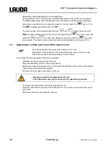
Press the set-point indicator key
.
Changing the set point: While the set point is being displayed, adjust the set point with the
keys
and
. Then confirm the new value with the key
(press for at least
2 s). Then the actual value is displayed again.
The LED "K 1" (next to the temperature display) illuminates when the solenoid valve "Cool-
ing liquid" is switched on.
The red alarm lamp illuminates when the overtemperature threshold is reached. Factory set-
ting 25 °C. The yellow alarm lamp illuminates when the level falls below the minimum bath
level. These disturbance signals as well as an operating signal and a "Remote on" contact
are present on the remote socket (back of the unit). For starting up, the unit must be con-
nected to a remote plug (connection on socket 15N between PIN 1 and 3).
The pump in
the unit continues to run even with a fault condition.
To limit the switching frequency of the solenoid valve a minimum stop period (delay time) of
12 s has been programmed at the factory.
Summary of Contents for UWT 10000
Page 1: ... 2SHUDWLQJ LQVWUXFWLRQV LUFXODWLRQ KHDW H FKDQJHUV 8 7 8 7 8 7 ...
Page 2: ......
Page 4: ......
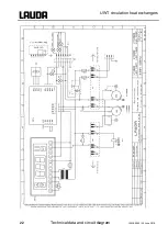
Page 24: ...UWT circulation heat exchangers 22 Technical data and circuit diagram YAWE0029 29 June 2018 ...
Page 26: ......
Page 27: ......


