UWT circulation heat exchangers
YAWE0029 / 29 June 2018
Technical data and circuit diagram
19
8
Technical data and circuit diagram
8.1
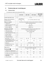
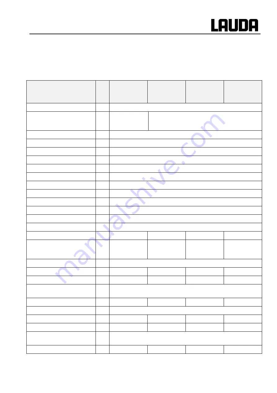
Technical data
The figures were determined according to DIN 12876.
UWT 3000
UWT 6000
UWT 10000
UWT 10000
with stronger
pump
Ambient temperature range
°C
5
– 40
Primary circuit and laboratory
circuit connections
G ¾ with hose
olive for ¾ " hos-
es
G 1 ¼ with hose olive for 1" hoses
Primary circuit data:
the primary circuit supplies cooling liquid provided by the customer
Cooling liquid
water or glycol/water mixture
Operating temperature range
°C
-10
– 20
Pressure absolute
bar
maximum 10
Pressure difference
bar
minimum 0.2
Laboratory circuit data:
the laboratory circuit (secondary circuit) supplies a load
Heat transfer liquid
water or glycol/water mixture
Temperature display
green 7-segment LED
Operating temperature range
°C
8
– 25
Setting resolution
°C
0.1
Display resolution
°C
0.1
Temperature stability
K
±1
Bath volume from to
L
7
– 12
35
– 45
35
– 45
35
– 45
Factory setting for volume
flow through bypass valve for
closed laboratory circuit
L/min
0.5
0.5
0.5
0.5
Pump type
Pressure pump
Discharge pressure, max.
bar
1.0
1.0
2.2
5.5
Discharge flow, max.
L/min
30
30
33
40
Safety devices
Overtemperature alarm, low level alarm, winding overtemperature and
overcurrent cut-off for the pump
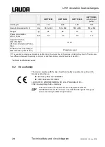
Cooling power
kW
3
6
10
10
at primary circuit temperature
°C
9
for primary cct. pressure drop
bar
0.12
0.05
0.07
0.07
for primary circuit volume flow L/min
6
16
20
20
for laboratory cct. feed
temperature
°C
14
for flow rate UWT
L/min
6
6
20
20
Summary of Contents for UWT 10000
Page 1: ... 2SHUDWLQJ LQVWUXFWLRQV LUFXODWLRQ KHDW H FKDQJHUV 8 7 8 7 8 7 ...
Page 2: ......
Page 4: ......
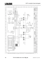
Page 24: ...UWT circulation heat exchangers 22 Technical data and circuit diagram YAWE0029 29 June 2018 ...
Page 26: ......
Page 27: ......


