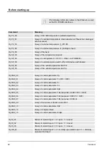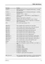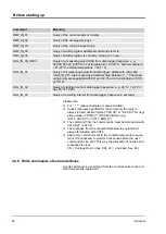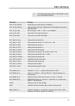
4.4.10
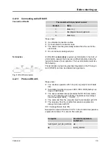
Connecting cable RS 485
Thermostat with 9-pin Sub-D socket
Contact
Data
1
Data A (-)
5
SG (Signal Ground) optional
6
Data B (+)
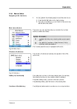
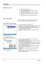
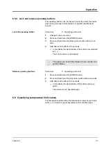
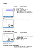
Please note:
n
Use shielded connection cables.
n
Connect shield to connector case.
n
The cables must be galvanically isolated from the rest of the
electronics.
n
Do not connect unassigned pins.
An RS 485 bus
absolutely
requires bus termination in the form of
a termination network that ensures a defined idle state during the
high-ohm phases of bus operation. The bus termination looks like
the following:
This termination network is generally integrated on the PC plug-in
card (RS 485) and can be activated using jumpers.
4.4.11
Protocol RS 485
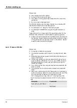
Please note:
n
The interface operates with 1 stop bit, no parity bit and 8 data
bits.
n
Selectable transmission speed: 2400, 4800, 9600 (factory set-
ting) or 19200 baud.
n
The device address always precedes the RS 485 commands.
Up to 127 addresses are possible. The address must always
have three digits (A000_... to A127_...).
n
The command from the computer must be terminated with CR.
n
The response from the constant temperature equipment is
always terminated with CR.
CR = Carriage Return (hex: 0D)
Example for setpoint transfer of 30.5°C to the constant temperature
equipment. Address 15 is used in this example.
Computer
Constant temperature
equipment
“A015_OUT_SP_00_30.5“CR
è
ç
“A015_OK“CR
Connection RS 485
Termination
Fig. 8: RS 485 termination
Before starting up
Variocool
39
Summary of Contents for VC 10000
Page 47: ...Fig 13 Menu structure part 1 Operation Variocool 47 ...
Page 103: ...General Variocool 103 ...
Page 110: ......
Page 111: ......

