6.11.1
Basics
Control
value
- Output value of the controller to compensate for the dif-
ference of actual value to setpoint (control deviation).
PID
con-
troller
- The PID controller operates very precisely and consists
of P, I and D parts.
Propor-
tional
range
Xp
- The proportional range Xp specifies the temperature
range in which the proportional part (P part) of the con-
troller is 0 – 100% of the maximum control value. For
example, if the control deviation is 2 K for Xp set to
10 K, the P part is 20% of the control control deviation.
In the case of a control deviation of 10 K and more, the
P part is 100 % of the control value.
Reset
time Tn
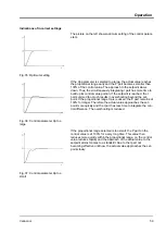
- The reset time is decisive for the integral part (I part) of
the control value. It specifies the interval in which an
existing control deviation is integrated. The larger Tn is,
the slower the control deviation is integrated. Thus, the
control is slower. A smaller Tn makes the control more
dynamic and finally results in oscillations.
Lead
time Tv
- The differential part (D part) of the control value is
formed from the lead time Tv. It influences the
approach speed of the actual value to the setpoint and
counteracts the P and I parts. The larger the lead time
Tv is set, the stronger the output signal is damped. As
rule of thumb. the following applies: Tv = Tn x 0.75.
An important prerequisite for acceptable control quality is well-
designed hydraulics. Therefore, an as good as possible connection
between the application to be temperature-controlled and the con-
stant temperature equipment must be established. This means:
n
Only use approved heat transfer liquids: water or water-glycol
mixture.
n
Use short tubes with large cross section. This reduces the flow
resistance. A lot of heat transfer liquid can circulate in a short
time, thus the circulation time is short.
n
Use bypass of the device to increase the flow rate of the heat
transfer liquid.
The viscosity of the heat transfer liquid changes very quickly with
the temperature. The liquids have higher viscosity at low tempera-
tures. Therefore, the control quality is generally worse at low tem-
peratures. For this reason, the controller should be set at the lower
end of the temperature range to be covered. If the control is stable
at low temperatures, then it is generally also stable at high temper-
atures. On the other hand, if a system is just still stable at high
temperatures, it is highly probable it will be unstable at low temper-
atures, i.e. it oscillates.
If, for example, the operating temperature range of a
system is -20 – 80 °C, then the controller setting should
take place at -10 – 20 °C.
Explanation of terms
Optimising hydraulics
Other precautions
Operation
Variocool
58
Summary of Contents for VC 10000
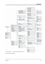
Page 47: ...Fig 13 Menu structure part 1 Operation Variocool 47 ...
Page 103: ...General Variocool 103 ...
Page 110: ......
Page 111: ......

