n
The UP, DOWN, RIGHT and LEFT arrow buttons can be used
to navigate in the screen.
n
A selection in the screen can be confirmed with the ENTER
button.
n
You can control can buttons functions shown in the display with
the soft keys.
3.4 Functional elements
3.4.1 Hydraulic circuit
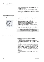
The hydraulic circuit designates the circuit through which the heat
transfer liquid flows.
The circuit basically consists of the following components:
n
Internal balancing bath with heat transfer liquid
n
Immersion pump to convey the heat transfer liquid to the
external consumer via the pump connections
n
Adjustable bypass with manometer to adjust the pump pres-
sure to the requirements of the external consumer.
n
Heater in the bath boiler to heat the heat transfer liquid (the
same devices are available without a heater)
n
Cooling coil in the bath boiler to cool the heat transfer liquid
Detailed information about the technical data of the
and characteristics of the pumps’ on page 96
.
3.4.2 Refrigeration unit
The refrigeration unit includes the following components:
n
Compressor
A reciprocating compressor is used in the refrigeration unit.
The compressor is equipped with a motor circuit breaker which
trips on the compressor temperature and compressor current
consumption.
n
Condenser
Depending on the device type, an air-cooled or water-cooled
condenser is used in the refrigeration unit. For air-cooled con-
densers, the heated air is discharged to the environment. The
fresh air is sucked in through the front of the device using a
fan, heated and discharged on the rear of the device. In water-
cooled condensers, the heat is dissipated via the cooling water
circuit.
n
Evaporator
In the internal bath, heat is discharged with a pipe coil evapo-
rator.
Fig. 5: Manometer
Device description
Variocool
18
Summary of Contents for VC 10000
Page 47: ...Fig 13 Menu structure part 1 Operation Variocool 47 ...
Page 103: ...General Variocool 103 ...
Page 110: ......
Page 111: ......

