4.4.4 Installing modules
Devices can be optionally supplemented with additional interface
modules. These can be installed in two different size module slots
on the front of the device.
n
Right module slot (approx. 51 mm x 27 mm) for RS232 /
RS485 module / analogue module / contact modules / Profibus
module
n
Left module slot (approx. 51 mm x 17 mm) for Pt100 / LiBus
module
This section is relevant for the following sample cases:
n
You would like to use an external temperature sensor.
n
You would like to transmit a signal such as the actual tem-
perature from an external consumer to the circulation chiller.
n
You would like to transmit a signal such as the setpoint tem-
perature to an external device.
n
You would like to use the Command remote control unit.
DANGER!
Contact with live parts
Electric shock
Disconnect the device from the mains power supply
before installing modules.
1.
Touch the grounded, bare metal stainless steel rear side of
the circulation chiller to discharge any electrostatic charge.
2.
Remove the module from the packaging.
3.
Switch off the circulation chiller and unplug the mains plug.
4.
The module slots are protected with a cover. Release the
screws on the cover for the appropriate module slot and
carefully remove the cover.
5.
Carefully detach the bus connection cable from the cover.
6.
Attach the bus connection cable - red plug to red socket.
The plug and the socket have a reverse-polarity-
proof design.
7.
Insert the module into the appropriate slot and fasten it using
the two Philips screws.
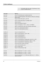
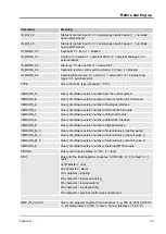
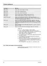
4.4.5 Read commands for serial interfaces
A read command is a request for current data from the control
centre to the constant temperature equipment.
Before starting up
Variocool
31
Summary of Contents for VC 10000
Page 47: ...Fig 13 Menu structure part 1 Operation Variocool 47 ...
Page 103: ...General Variocool 103 ...
Page 110: ......
Page 111: ......


