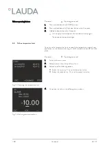
1.
Switch to the main menu.
2.
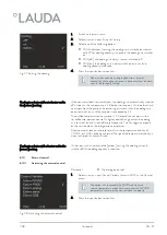
Select the menu item
Setup
Cooling
.
3.
Select one of the following options:
n
With the [autom.] setting, the cooling unit is switched automati-
cally. When cooling capacity is required, the cooling unit switches
on.
n
With [off], the cooling unit always remains switched off.
n
With [on], the cooling unit is always switched on, even if no
cooling capacity is required.
4.
Press the input button to confirm.
Under certain conditions, lengthy downtimes (several
minutes) of the cooling unit occur in devices without a heater
when in the
[autom.]
setting.
If the consumer load is extremely low, the cooling unit automatically switches
off as soon as the temperature is 2 K below the set point. On the other hand,
heat input from the pump and consuming unit means that the cooling unit
does not switch on until the set point is exceeded by 2 K.
The outflow temperature always moves ±2 K around the set point in this
so-called two-position control. A tighter control range causes the cooling
unit to switch on and switch off more frequently. This has negative impacts
on the service life of the refrigeration compressor.
A low consumer load can therefore result in the temperature stability of
±0.05 K or ±0.1 K not being achieved. The specified temperature stability is
always achieved if a heater is used.
On devices with a heater and the [autom.] setting, the cooling unit only
switches off if no cooling capacity is required.
6.10
External control
6.10.1
Activating the external control
Personnel:
n
Operating personnel
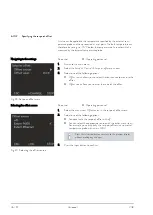
1.
Select the menu item
Control Variable
extern Pt100
in the Control
menu.
This option is only available if a Pt100 module for an
external temperature probe has been connected. A Pt100
temperature sensor must be connected to the module.
2.
Press the input button to confirm.
Fig. 27: Setting the cooling
Cooling in a device without a heater and in
the [autom.] setting
Cooling in a device with a heater and in the
[autom.] setting
Fig. 28: Activating the external control
V08
Variocool
45 / 97
Summary of Contents for VC 1200
Page 38: ...Fig 13 Menu structure part 2 Menu structure for Graph Clock and Standby V08 Variocool 38 97 ...
Page 98: ......
Page 99: ......


