Functions
Part 1 • Page 6-5
Part 1 – Operating Instructions
Rev. 4.00 December 2014
Software version 1.04
EcoRO Dia I/II (HT)
Part 1 • Chapt
er 6
6.2
Functions
6.2.1
Water supply
Feed water is made available through a pretreatment installation with the appropriate capacity. It includes
softener, activated carbon filter and pre-filter systems,
To protect the reverse osmosis system, mechanical contamination that is still present is removed by
means of a filter element (VF) on the RO rack.
6.2.2
Supply tank
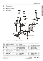
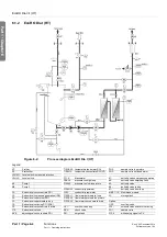
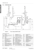
The pre-treated water enters the supply tank (
VL
) through feed valve
Y10
. The water level is recorded and
controlled using level switch
LSHL2
.
The built-in centrifugal pumps are safeguarded against lack of water by level switch
LSHAL1
(pump pro-
tection). If the level drops below the lower switchpoint, the pumps switch off.
The following are connected to the supply tank:
•
Internal circulation via
Y2
•
Soft water intake via
Y10
•
Loop return via
UV1
•
Soft control (optional)
•
Overflow
•
Bypass valve
Y30
to the overflow valve for the loop return (optional)
•
Ventilation and venting filter (tank respiration)
6.2.3
Single stage reverse osmosis system EcoRO Dia I (HT)
The raw water flows over a 5 µm pre-filter and enters the free intake to the supply tank
VL
via the
solenoid
Y10
.
From there, it is delivered by means of pumps
M1
and
M2
to the membrane modules
MM1.1
and
MM1.2
by passing through a reverse osmosis membrane. The “feed flow” is divided into the concentrate flow and,
following passage of the membrane barrier, the permeate flow.
The concentrate flow leaves the membrane module through the needle valve
NV4
which restricts the
volume of water discharged and ensures a constant production pressure. The concentrate pressure can
be read off on manometer
PI2
.
The concentrate flow regulated in this way is either re-circulated through solenoid valve
Y2
back into the
supply tank or is conducted to the drain outlet through solenoid
Y9
. The cycle rate of Y2/Y9 and thus the
regulation of the concentrate amount to be discharged depends on the amount of permeate removed and
the set yield factor WCF. The amount of concentrate to be discharged is calculated from the upstream
FISCAL1
and return (
FISCAL2
) of the loop and recorded using
FISCAL3
.
The permeate flows through the opened solenoid Y5 and past PSAH1 and CISAHH1, whereby the para-
meters permeate pressure and quality are monitored. The amount of permeate is recorded by flowmeter
FISCAL1 before it enters the loop. In larger systems, part of the permeate amount produced flows back
into the supply tank through the overflow valve UV2 if the amount removed is too low in order to keep the
loop pressure constant.
NOTICE
Technical overview: see
part 2, chapter 7.13.2 “Operating modes”.
IMPORTANT Due to operational safety, the positions and switchpoints of the level switches LSHAL1 and
LSHL2 may not be changed.

