Rev. 4.00 December 2014
Software version 1.04
Part 1 • Page 7-4
Description of components
Part 1 – Operating Instructions
EcoRO Dia I/II (HT)
Part 1 • Chapter 7
7.3.2
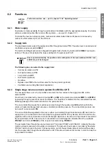
Conductivity display
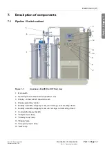
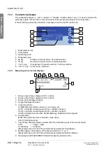
The conductivity display (
part 1, chapter 7.1 “Pipeline / Switch cabinet”, pos. 7) is used to monitor the
permeate quality. It shows the current conductivity of the produced permeate in the loop intake.
If the set limiting values are exceeded, a message is sent to the RO control unit.
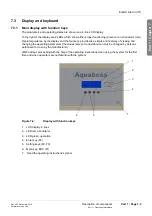
1. Measurement unit
2. Temperature
3. Operating mode
4. Measured value
5.
▲
key
Increase numerical value / Forward selection
6.
▼
key
Decrease numerical value / Forward selection
7.
<PGM>
key
Change level / Forward selection / Confirm selection
8.
<EXIT>
key
Cancel entry / Exit level
7.3.2.1
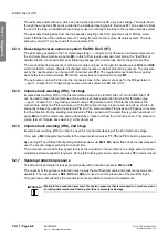
Measuring mode (normal display)
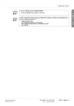
1. Binary output (relay): displayed if K1 is active
2. Binary output (relay): displayed if K2 is active
3. Binary input: displayed if active
4. Keypad: displayed if locked
5. Instrument status:
ALARM (flashing): Broken sensor or over range, etc.
AL R1: Controller monitoring alarm from controller channel 1
AL R2: Controller monitoring alarm from controller channel 2
CALIB: Calibration mode active CALIB (flashing): Calibration timer elapsed
6. Output mode
MAN.: Manual mode and/or simulation mode active
HOLD: Hold mode active
7. Top display: Measured value calculated from the standard signal at the input example:
TDS
→
3 mg/l = 3 ppm
Conductivity
→
5,5 µS/cm
(Measured value and unit of the variable set by parameter “Top display”)
8. Bottom display: Temperature of the sample medium in °C or °F
(Measured value and unit of the variable set by parameter “Bottom display”)
9. Operating mode MEASURING: Standard measuring mode is active
1
2
3
4
6
5
7
8
K1 K2 E1
ALARM MAN
MEASURING
3
l
/
g
m
F
°
4
,
5
5
1
2
3
4
5
6
7
8
9

