LAUNCH
X-431 PAD V
User's Manual
67
1
3
2
5
4
6
7
8
9
10
11
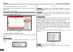
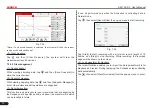
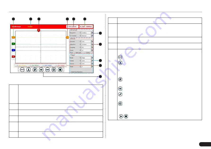
Fig. 7-25
1
Displays the CH1/CH2/CH3/CH4 information:
Readout shows the coupling and vertical scale factors of the
channels.
A “B” icon indicates that the channel is bandwidth limited.
2
Working mode
3
Horizontal trigger position marker
4
Edge trigger level marker
5
Displays the trigger information, including the edge trigger
slope, source and level.
6
Sample rate
7
Horizontal Settings Panel: Controls the time base.
8
Vertical Settings Panel: Controls the amplitude of the
displayed signal. User can change the volt/div, coupling and
probe attenuation of the CH1/CH2/CH3/CH4.
9
Trigger Settings Panel: Controls the start event of the sweep.
10 Channel Selection Button
11
Function Menu
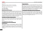
[Auto]: It indicates auto trigger setting.
[Ref]: There are expert reference and base reference
available. Expert reference enables you to recall your
customized expert database, whereas base reference
provides automatic pre-setting function of specialized sensors.
[File]: Provides save snapshot, snapshot manager,
waveform record and waveform replay.
[View]: Calibration and display settings are available.
[Measure]: Includes signal source measurement, horizontal
measurement, vertical measurement and clear measurement.
[Settings]: Shows/hides the parameter settings area
including horizontal settings, vertical settings and trigger
settings.
/
[Start/Stop]: Starts/stops collecting waveforms.
7.3.4 Operations
7.3.4.1 Channel selection and attributes setting
<1> Channel selection


