LAUNCH
Installation Instruction for Economical Symmetric Floor-plate 2-post Lift
8
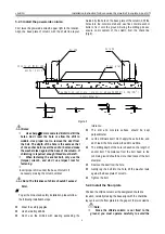
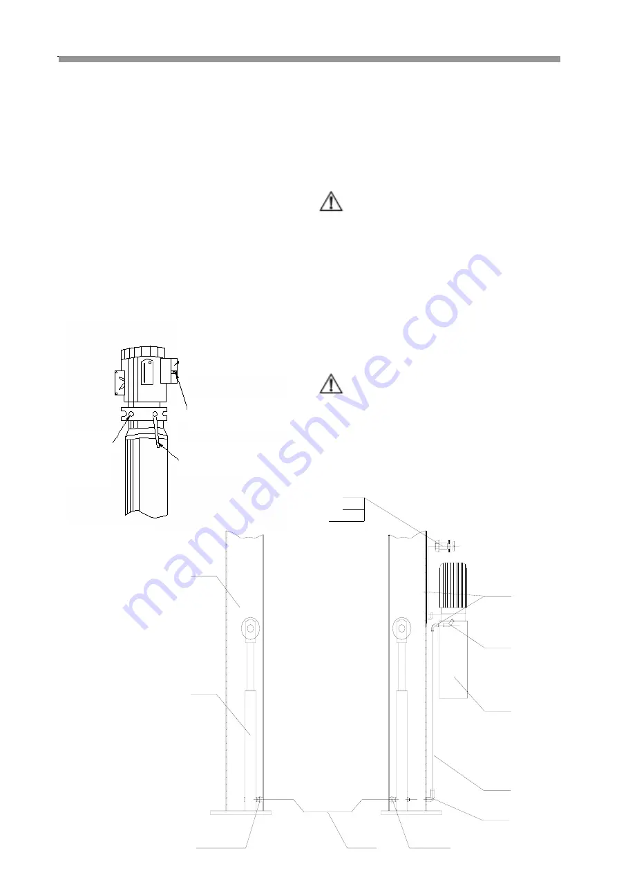
5.2.8 Connecting the power supply
(
As
Figure 7
)
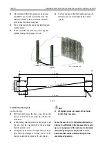
Dismantle the sealing cover of the electrical box on the
power unit and do the wiring according to the circuit diagram;
the power supply switch is required to be installed near the
lift for convenient disconnecting the power supply during
maintenance or in case of emergency. The motor damage
caused by wrong wiring is not warranted. Please contact the
manufacturer for the electrical issues. Ensure that the oil
tank is full; don’t operate where there is no oil. After
pressing the start button, if the motor doesn’t run or the
abnormal noise or heat occurs, the machine shall be
immediately stopped to check the correctness of the
electrical connections.
Figure 7
Note
:
If the lift is used outdoors, it is recommended to set a
cover on the power unit; such damages to the motors
caused by the water or other liquids like the detergent,
acid, etc, are not covered by warranty.
5.2.9 Connecting the hydraulic lines
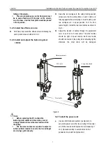
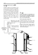
TLT235/240SB hydraulic lines is shown in Figure 8; please
perform the connection according to the diagram and all the
fittings shall be tightened in order to prevent the oil leakage.
Note: If the hose shall be installed through the
column, ensure that the hose passage will not
interfere with any moving parts.
Please remove the
plastic plug from here
and install one
hydraulic fitting
Start button operating switch
(Lifting operation by pressing)
Lowering handle
(Lowering operation by pressing)
Please refer to the circuit
diagram attached with the motor
in order to acquire the correct
wiring instruction.
Fitting
Oil cylinder
Column
Hydr hose
90
°
fitting
Fitting
Power unit
Hydr hose
M10
×
25 Bolts
2 sets
φ
10 Ring gasket
φ
10 Flat gasket
Hydr hose
Turn around fitting


