Launch
X-631 Wheel Aligner Maintenance Manual
Probe Rod Calibration
5-4
c)
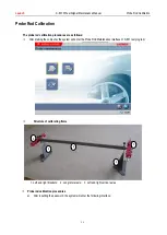
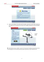
Calibration for 1# and 2# clinometer and end CCD camera
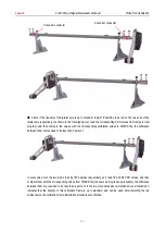
First, please remove the two vertical axles from the small calibration frame, and then install 1# and 2# probe rods at
the two ends of the long lateral axle of calibration frame and adjust them level, as shown in the following figure:
d)
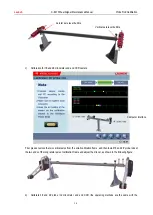
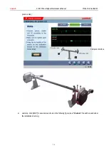
Calibrate 3# and 4# probe rod clinometer and end CCD (the operating methods are the same with the
Computer interface
Lateral axle level bubble
横轴水平泡
Vertical axle level bubble
纵轴水平泡

