In each installation, an access panel must
be provided near the final pump location for
servicing the pump and power panel. This ac-
cess may be through the wall or platform
apron. In the case of a sunken installation,
access may be through the ceiling below the
bathtub.
OPTIONAL: POP-OUT SKIRT
INSTALLATION
NOTE: The skirt is to be installed immedi-
ately after the plumbing and electrical work
have been completed. Do not wait until the
drywall has been completed, as the skirt is the
same length as the tub.
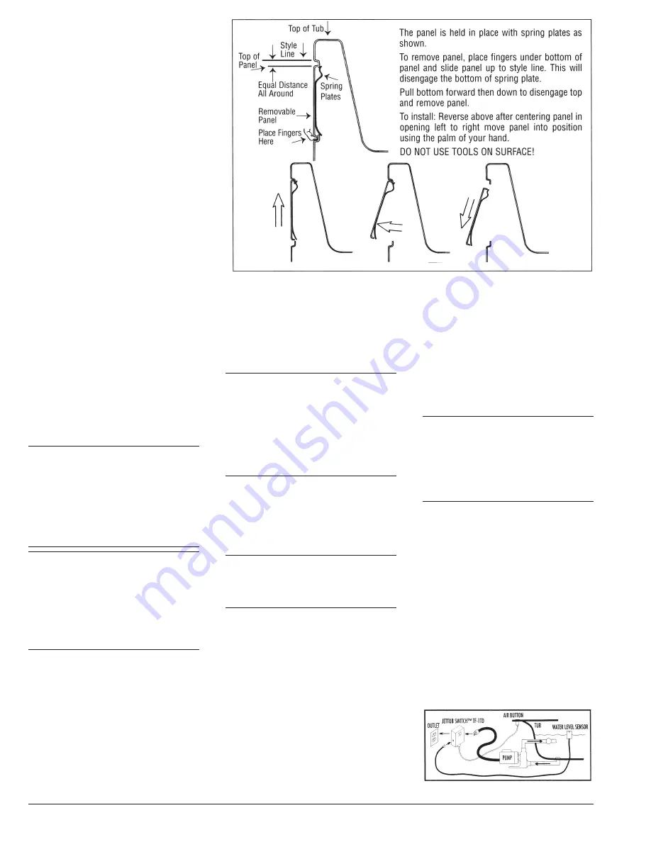
1. Remove pop-out panel from skirt frame.
Do not use metal objects to pry off the
panel. (See diagram.)
2. Place skirt frame under tub rim into cor-
rect placement.
3. Mark top and bottom inside of skirt frame
at center.
4. Remove skirt frame.
5. Place 1x or 2x vertical support at center
of tub, just touching inside marks from
skirt frame.
6. Place skirt frame back under tub.
7. Anchor ends of skirt frame to studs
through corner bead and anchor bottom
of skirt frame to the sub floor.
8. Place pop-out panel on skirt frame.
9. Finish drywall--flooring.
WIRING INSTRUCTIONS
Rough in the wiring on a single 120VAC, 20
AMP, GFCI protected dedicated circuit for each
accessory installed on the tub.
All Whirlpool Systems and Inline Heaters are
equipped with a molded plug on the end of a
power supply cord.
Install a separate, dedicated 120VAC, 20 AMP
GFCI protected electrical wall plug outlet inside
the access panel for each accessory equipped
on the tub.
EXAMPLE: If the tub is equipped with a whirl-
pool system only, then one GFCI wall plug out-
let is necessary. If the tub is equipped with
both whirlpool system and an inline heater then
two separate circuits with GFCI wall plug out-
IMPORTANT WARNING:
ALL POWER SUPPLIES MUST BE DIS-
CONNECTED BEFORE SERVICING.
OPTIONAL: INLINE HEATER
WIRING
(See Diagram A-2)
IMPORTANT: Electric inline heaters are con-
trolled by a “pressure switch,” which is pre-
plumbed into the heater. This switch allows
the heater to operate only when there is suffi-
cient water flowing through the system. DO
NOT BYPASS THE SWITCH. This option is
equipped with a molded plug on the end of a
power supply cord. Check your local codes,
simply install a 120VAC, 20AMP GFCI pro-
tected dedicated circuit wall outlet to within 1
½ feet from the heater unit. Plug the cord into
the outlet.
This option is designed to MAINTAIN tempera-
ture, but, will increase the temperature of the
water in the system to the factory preset high
limit switch of 104 degrees F over an extended
period of time. The high limit cannot be in-
creased adjusting the heater thermostat. The
heater is operated by a pressure switch. Every
time the bath is turned on the heater will auto-
matically turn on to MAINTAIN water tempera-
ture. The heater tube will not feel hot until tem-
perature of water is hot, as the flow of cooler
water will keep the jacket cool.
WARNING:
ALL BATHTUBS
EQUIPPED WITH AN INLINE HEATER
REQUIRES TWO DEDICATED CIR-
CUITS. ONE FOR THE WHIRLPOOL
SYSTEM AND ONE FOR OPTIONAL
INLINE HEATER.
OPTIONAL: MOUNTAIN AIR
SWITCH
(See Diagram below)
Plug the Mountain Air Switch
TM
unit into the
wall socket, and then plug the pump motor’s
power cord into the Mountain Air Switch unit.
The Water Level Sensor is a control that
senses water level through a tub wall. It will
prevent pump damage from “dry firing” (run-
ning without water) and jet overspray by al-
lowing the pump to be operated only with the
proper tub water level. An indicator light is
provided on the front face, and will be on when
the tub water is at or above the actuation level
of the Water Level Sensor. There is a timer that
will automatically turn off the whirlpool after
20 minutes.
DANGER:
ALL CIRCUITS CON-
NECTED TO THIS UNIT MUST BE
EQUIPPED WITH GROUND FAULT CIR-
CUIT INTERRUPTER (GFCI) PROTEC-
TION. IT IS THE TUB INSTALLER’S RE-
SPONSIBILITY TO WIRE THE CIRCUIT
WITH (GFCI) PROTECTION.
WARNING:
ALL ELECTRICAL
CONNECTIONS MUST BE MADE BY A
LICENSED CERTIFIED ELECTRICIAN-
IN ACCORDANCE WITH THE REQUIRE-
MENTS OF THE NATIONAL ELECTRICAL
CODE AND APPLICABLE STATE AND
LOCAL CODES AND PROCEDURES.
lets are required.
NOTE: Count the number of accessories be-
fore installing the GFCI wall outlets.
NOTE: The power supply cords equipped on
each accessory are only 2½ ft. long so locate
the GFCI wall outlet within 1½ ft. of the intended
accessory.
INSTALLATION & OWNER’S MANUAL
4
OPTIONAL: MOUNTAIN AIR SWITCH
DANGER: DO NOT splice a longer cord to the
power supply cord and DO NOT connect to an
extension cord.
The connection for each accessory is com-
pleted simply by inserting the molded plug into
the intended GFCI wall outlet.
IMPORTANT:
PLEASE BE
AWARE THAT WHEN ORDERING MUL-
TIPLE OPTIONS, MORE THAN ONE
ELECTRICAL OUTLET MAY BE RE-
QUIRED AND THERE MAY BE MORE
THAN ONE MOTOR LOCATION THAT
NEEDS ACCESS.
Summary of Contents for Colony Series
Page 1: ... E157308 ...


