background image

18

TROUBLESHOOTING

PROBLEM

POSSIBLE CAUSE

CORRECTIVE ACTION

Pilot won’t light

Pilot won’t stay lit

Burner won’t light

Burner flame is low

Carbon build-up

Thick black smoke

Heater won’t  work

and the POWER 

indicator won’t  light 

when heater is started

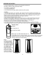
Ignition batteries low or faulty. The POWER 

button has not been pressed for 2 seconds

Remote control faulty or batteries low.

Cables faulty or loosen.

Replace batteries. Press POWER button 

for 2 seconds, release and press again to 

start ignition. Replace remote control or 

batteries. Repair or replace.

Gas odour with extreme 

yellow tipping of flame.

Heater glow is 

excessively uneven.

Heater makes 

popping noises.

Cylinder valve is closed

Open valve

Blockage in orifice or pilot tube

Air in gas line

Low gas pressure with cylinder valve 

fully open
Igniter fails

Propane cylinder is frosted over

Blockage in orifice

Control knob is not in ON position

Gas pressure is low

Control knob fully ON

Dirt or film on reflector and burner screen

Blockage in burner

Blockage in orifice

Clean burner and orifices

Burner titl

Spiders and insects

Spiders and insects

Bad regulator

Change the regulator

Spiders and insects

Adjust the position of control box assembly

Remove blockage and clean burner

inside and outside

Check burner and orifices for 

blockage
Clean reflector and burner screen

Clean burner and orifices

Clean burner and orifices

Outdoor temperature is less than 40ºF and 

tank is less than 1/4 full

Turn cylinder valve OFF and replace

cylinder

Use a full cylinder

Turn control knob to ON

Dirt built up around pilot
Connection between gas valve and pilot 

assembly is loose
Thermocouple is not operating correctly

Anti tilt switch could be faulty, or wires not connected properly

Clean or replace orifice or 

pilot tube
Open gas line and bleed it

(pressing control knob in) for no

more than 1 - 2 minutes or until

you smell gas
Turn cylinder valve OFF and replace 

cylinder
Use match to light pilot; obtain new 

igniter and replace
Clean dirt from around pilot
Tighten connection and perform 

leak check
Replace thermocouple

Replace anti tilt switch/Connect wire properly

Wait until the propane cylinder 

warms up and becomes unfrosted
Clear blockage

Note: Heater operates 

at reduced efficiency 

below 40ºF (5ºC) 

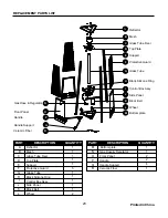
Summary of Contents for Lava 2G

Page 1: ...LAVA 2G Outdoor Flame Heater New Model 2014 66 000BTU Instruction Manual C E R T I F I E D DE S I GN 10 YEAR LIMITED W ARRANT Y www lavaheat com ...

Page 2: ...l not be stored in the vicinity of this or any other appliance WARNING Improper installation adjustment alteration service or maintenance can cause property damage injury or death Read the installation operation and maintenance instructions thoroughly before installing or servicing this equipment WARNING For Outdoor Use Only WARNING WARNING indicates an imminently hazardous situation which if not ...

Page 3: ...otective Guard F Glass Tube G Control Box Assy I Black Silicone Ring H Side Panel J Bottom plate M Wheel N O I T P I R C S E D T R A P QUANTITY A Reflector 1 B Mesh 1 C Glass Tube Fixer D Top Plate E Support F Protective Guard 1 1 1 3 G 1 H 1 I Block Belt Side Panel Black Silicone Ring Glass Tube 1 J K Wheel L 1 1 2 Control Box Assy L Block Belt K Gas Hose Regulator Front Panel O Handle P Handle S...

Page 4: ...is manual Always heed these precautions as they are essential when using any mechanical or fueled equipment DANGER DANGER indicates an imminently hazardous situation which if not avoided will result in death or serious injury DANGER Failure to comply with the precautions and instructions provided with this heater can result in death serious bodily injury and property loss or damage from hazards of...

Page 5: ...6315 7 15 0155 9 3 515 63 5 5 6 0 9 3 44 3 769 5 318 1 6 56 0 9 15 9 1 0 01 0 65 5 1514 4 0 9 3 9 5 964 64 1 3 4 91 3 09 964 0 1 6 964 0 67 556 69 9 01 0 4 4 6 6 9 0 9 0 2 1 0 6 9 36 3 19 0691 1 6 0 8 165 6 0 9 0 9 5 9 6 95 0 6 3 5 0 796 15 796 69 7 1 1 6 9 36 3 0691 1 5 1 6 6 0 56 36 3 6 1 6336 165 3 3 6 5 5 15 33 165 4 65 694 6 36 3 6 56 36 3 6 1 6336 0 99 5 165 3 5 9 6 DANGER 01 7731 5 5 796 9 ...

Page 6: ...away from the original leak Use only propane gas set up for vapor withdrawal 614 14 75 2412 0 5 0 1 2 0 9 6 1 ordinances and codes or with ANS NFPA 58 Turn off propane when not in use WARNING 46 4 0 0 7 65 61 6 4 5 1 574 temperatures Stay away from these surfaces to avoid burning skin or igniting clothing 4 7 572 48 5 170 4 0 9 0 0 6 8 0 6 of the heater 1 016 0 16 0 14 0 16 4 6 4 5 from the heater...

Page 7: ... HH CC x 3 x 3 Nut M8 Stud II x 3 Cap nut M8 HH DD x 3 Screw M5 X 12 1 Heater is preassembled at the factory User needs to complete a couple of assembly procedures to make the appliance operational Please ensure all transit protection foam cardboard bubble wrap etc is removed In the next few steps you will be shown how to properly remove the bubble wrap material used to protect the boroscilate gla...

Page 8: ...en remove the protective steel guard from its upper supports slots Hardware Used DD GG GG x 3 x 3 x 1 Fixing Bracket PP Philips screwdriver Screw M5 X 12 E 4 Carefully remove the boroscilate glass tube F situated between center of the top plate and the control box assembly Simply slide the unit up and out from its position Unwrap the bubble wrap material from the glass IMPORTANT PLEASE SAFELY UNWR...

Page 9: ...ls from the unit you will need to place the unit back in its original proper order We will revisit the last several steps in reverse order First re install the boroscilate glass tube F Carefully install the boroscilate glass tube between center of the top plate and the control box assembly as illustrated Make sure to place the lower end of the glass tube between the three metal clips located on th...

Page 10: ...5X12 DD CC II DD HH CC x 3 x 3 Nut M8 Stud II x 3 Cap nut M8 HH DD x 3 Screw M5 X 12 8 8 Use a secured step ladder or lean the heater carefully and attach the 3pcs small flat washer ĭ8 BB on top of the heater Place a washer on each reflector stud then install the reflector hood and lastly fasten the reflector with another washer and wing nut AA Return the heater gently to upright position if appli...

Page 11: ... plate using 8pcs M6x10 screws CC 10 Open the front panel and then open the lid of the battery compartment and insert 2 batteries type D flashlight batteries DC1 5v each considering the correct polarity Close the lid Return the side panel in place Hardware Used x 1 x 8 CC DD Bolt M6 X 10 Wrench ...

Page 12: ...ust have a connection device compatible with the connection for the appliance The cylinder used must include a collar to protect the cylinder valve Never connect an unregulated propane cylinder to the heater Screw regulator onto gas hose Do not cross thread Tighten securely Attach regulator to cylinder Complete attachment Install cylinder and secure with the propane tank strap tightly Do not store...

Page 13: ...les continue appearing the hose should be returned to the place of purchase 3 If leak is at regulator cylinder valve connection disconnect reconnect and perform another leak check Apply the soapy solution to all hose valve connections If you continue to see bubbles after several attempts cylinder valve is defective and should be returned to cylinder s place of purchase If NO bubbles appear at any ...

Page 14: ...ter is equipped with a pilot light that allows for safer startups and shutdowns Pilot must be lit before main burner can be started HDWHU FDQ EH RSHUDWHG E LQIUDUHG UHPRWH FRQWURO RU GLUHFWO RQ WKH FRQWURO XQLW 23 5 7 21 1 5 5 5 027 21752 72 7851 21 7 7 5 7XUQ RQ WKH YDOYH RI WKH JDV VXSSO F OLQGHU ROG WKH UHPRWH FRQWURO LQ RXU KDQG DQG SRLQW LW WRZDUG WKH FRQWURO XQLW DQJOH RI UHFHSWLRQ LV DQG PH...

Page 15: ...he heater are free and clear of debris If debris spider or insect nests are found clean the holes with heavy duty pipe cleaner or compressed air 5 Always keep a dry chemical fire extinguisher readily available 6 For safety always allow a 5 minute complete shut off period before re lighting a hot heater 7 Avoid repeated ignition attempts if ignition doesn t start except for first time or new gas bo...

Page 16: ...f excessive yellow flame is detected turn off heater and consult Troubleshooting on page 18 B DIRECT OPERATION ON THE CONTROL UNIT TO TURN ON THE HEATER 1 Turn on the valve of the gas supply cylinder 2 Press the POWER button for 2 seconds release and press again to start ignition 3 Press the POWER button to switch to the temperature heat setting Every time the POWER button is pressed it will switc...

Page 17: ...n 21 More frequent cleaning may be required as necessary It is imperative that control compartment burner and circulating air passageways of the heater be kept clean After Operation 1 Gas control is in OFF position 2 Gas Tank valve is OFF 3 Disconnect Gas cylinder WARNING FOR YOUR SAFETY R 127 WRXFK RU PRYH KHDWHU IRU DW OHDVW PLQXWHV after use 5HIOHFWRU LV KRW WR WKH WRXFK OORZ UHIOHFWRU WR FRRO ...

Page 18: ...nce of your heater Apply to exterior surfaces from the pole down Do not apply to emitter screen or domes Storage Between uses Turn Control Knob OFF Disconnect LP cylinder Store heater upright in an area sheltered from direct contact with inclement weather such as rain sleet hail snow dust and debris If desired cover heater to protect exterior surfaces and to help prevent build up in air passages N...

Page 19: ...ean burner and orifices Burner titl Spiders and insects Spiders and insects Bad regulator Change the regulator Spiders and insects Adjust the position of control box assembly Remove blockage and clean burner inside and outside Check burner and orifices for blockage Clean reflector and burner screen Clean burner and orifices Clean burner and orifices Outdoor temperature is less than 40ºF and tank i...

Page 20: ...l consumer purchaser only and excludes industrial commercial or business use of the product product damage due to shipment or failure which results from alteration product abuse or product misuse whether performed by a contractor service company or consumer We will not be responsible for labor charges and or damage incurred in installation repair or replace ment nor for incidental or consequential...

Page 21: ...e Fixer C Protective Guard F Glass Tube G Control Box Assy I Black Silicone Ring H Side Panel J Bottom plate M Wheel N O I T P I R C S E D T R A P QUANTITY A Reflector 1 B Mesh 1 C Glass Tube Fixer D Top Plate E Support F Protective Guard 1 1 1 3 G 1 H 1 I Block Belt Side Panel Black Silicone Ring Glass Tube 1 J K Wheel L 1 1 2 Control Box Assy L Block Belt K Gas Hose Regulator Front Panel O Handl...

Page 22: ......

Reviews: