background image

19 


Counter Instructions 


In the normal operation mode after powering up the unit, the distance count is displayed on the screen 
along with the camera picture.  The 

CLEAR

 switch (Figure 7 Item 8) clears the count to 0000.00ft (or 

0000.000m). 

The 

MENU

 switch (Figure 7 Item 8) sequences through six on-screen modes as follows: 


Preset 

. . . . . . . . . . . . . .  Preset specific count 

Position

. . . . . . . . . . . . .  Position count on screen 

Standard

. . . . . . . . . . . .  Standard of Feet or Meters 

CAL by Reel

. . . . . . . . . .  Calibrate by Reel 

CAL by CNT/REV

. . . . . .  Calibrate by count per foot 

Status

. . . . . . . . . . . . . . . Status of Control Unit Temperature and Voltage 


NOTE:

 in the normal operation mode, the 

INC

 and 

DEC

 switches (Figure 7 Item 9) do not have any 

function; however, they do perform various functions in the other modes. 

 
Preset Mode


The Preset mode allows the distance count to be preset to a 
specific number.  This provides a way to initially start counting 
with a number other than zero.   
 
The 

INC

 switch (Figure 7 Item 9) increases the count.   

The 

DEC

 switch (Figure 7 Item 9) decreases the count.   

The 

CLEAR

 switch (Figure 7 Item 8) sets the count to zero. 


NOTE: 

Holding down the 

INC/DEC

 (Figure 7 Item 9) switch causes it to increase or decrease repeatedly.   


Position Mode 

The Position mode allows positioning of the distance count to 
be one of five positions: top left, bottom left, bottom right, 
top right, or centered.   
 
The 

INC

 switch (Figure 7 Item 9) sequentially changes the 

position by moving the positions in a clockwise sequence.  
The 

DEC

 switch (Figure 7 Item 9) sequentially changes the position in a counter-clockwise sequence.   

The 

CLEAR

 switch (Figure 7 Item 8) 

sets the position to the ‘home’ pos

ition which is at the top left (TL). 


 Preset 
 INC: Increment 

 DEC: Decrement 
 CLR: Zero 


 Position 
 INC: CW 

 DEC: CCW 
 CLR: Home (TL) 


Summary of Contents for R-CAM 1000 XLT

Page 1: ...LAVAL UNDERGROUND SURVEYS R CAM 1000 1300 XLT OPERATION MANUAL LAVAL UNDERGROUND SURVEYS 2476 North Bundy Drive Fresno Ca 93727 Phone 559 251 1396 Fax 559 251 2096 www lavalunderground com ...

Page 2: ...era 6 Reel Assembly 8 Power Supply 8 Control Unit 9 DVR Guide 12 Keyboard Functions 13 Getting Started 13 Play Video 14 View Snapshots 14 Overlays 14 File Management 15 Setup 16 Helpful DVR Tips 18 Counter Instructions 19 Preset Mode 19 Position Mode 19 Standard Mode 20 CAL by Reel Mode 20 CAL by CNT REV Mode 20 Status Mode 21 Water Well Clarification 22 Troubleshooting Guide 24 WARRANTY 26 ...

Page 3: ...he following Centering Bands with Collars Camera Camera Case Winch Auxiliary Power Cable Control Cable Power Cable 12 Volt Battery Control Unit Battery Charger TriLight Lens Shield Optional Accessories Sold Separately See www lavalparts com for more details Cable Head Repair Kit ...

Page 4: ...se and replace the locking pin 4 Install the shelf on to the Reel Handle using the included Hardware 5 Ensure the REEL CONTROL Power Figure 4 Item 1 and CAM CONTROL Power Figure 4 Item 2 Switches are in the OFF Position 6 Position the Reel Control FORWARD STOP REVERSE Switch Figure 4 Item 3 to STOP and the SPEED Control Dial Figure 4 Item 4 to MIN 7 Connect the Reel Control and Power Cable Figure ...

Page 5: ... on a regular basis Use a NEMA rated O rings lubricant 7 Slide the Centering Band Assy Figure 3 Item 2 and Upper Support Tube Figure 3 Item 3 beveled end first over and past the Cable head Figure 3 Item 1 Connect the Twist Locking Cable head Connector to the Camera by carefully aligning the keyway on the connectors together and twisting the lock until seated The cable head connector should only be...

Page 6: ... with the view selected The light intensity of the view selected can be changed by pressing LIGHT this will cycle through 5 light intensity levels Check the rotation by using the Cam Control FORWARD REVERSE Switch Figure 4 Item 10 both the Down View and Side Views will rotate 3 Rewind any excess cable by using the Reel Control functions Figure 4 Items 1 3 and 4 to position the Camera in the well n...

Page 7: ...N VIEW and SIDE VIEW while the Camera is rotating 7 Loss of power will reset the On Screen Counter 8 The 12 VDC Battery Pack provided with the system should be charged for at least 24 hours prior to the first survey 9 To ensure longer battery life charge the battery after each operation 10 Monitor the Voltmeter while in use The system will not operate below 10 5V 11 In the event of a Battery Pack ...

Page 8: ...e Camera with fresh water and wipe clean after use Ensure the camera is free of unwanted oil and contaminates If necessary use mild dish soap to clean the camera Prior to and after conducting each survey inspect the glass ports on the side view and down view for any cracks or debris in crevices If necessary use household glass cleaner to clean the viewing ports Inspect the cable head connection po...

Page 9: ...ot compatible with other types of closed circuit survey systems A single coaxial Cable head Connector on the rear of the Camera is connected to the Cable by a watertight pressure rated connector The R Cam Control Unit provides all the controls to operate the Camera and Reel Assembly equipped with a 9 LCD Color Video Monitor and embedded DVR with internal memory A 12 VDC rechargeable Absorbed Glass...

Page 10: ...tector and Support Tube 4 Upper Centering Band Collar 5 Down View Lens Port 6 Down View LED Lighting Port 7 Glass Side View Lens and LED Lighting Port 8 Camera Housing 9 Set Screw for Centering Band Collar 10 Screw for Centering Band 8 2 4 9 5 6 3 1 7 10 Figure 5 ...

Page 11: ...ing the Camera during the survey An Electronic Encoder Figure 6 Item 3 is mounted at the Boom head and is used to display accurate footage information of the Camera s depth on the Control Unit Video Monitor When the system is not in use the Boom Arm can be repositioned for easier storage by simply removing the locking pin Figure 6 Item 4 at the base of the Boom Arm removing and rotating the Arm 18...

Page 12: ...it will not hold a charge When charging ENSURE SURE THE FUSE IS IN THE BATTERY When storing the system for an extended period of time fully charge the battery for 24 hours using the supplied charging cable Then remove the fuse and store in a fully charged state Repeat this procedure every 30 days to maintain a healthy battery life Control Unit The R CAM Control Unit is a lightweight portable hard ...

Page 13: ...ure 7 Item 8 is used to set the depth counter to zero 0000 00ft after positioning the Camera near the top of the well prior to the start of the survey Loss of power to the system will reset the depth counter to zero The REEL CONTROL ON OFF Switch Figure 7 Item 12 routes power to the Motor Drive controls when switched to the ON position The FORWARD STOP REVERSE Switch Figure 7 Item 10 controls the ...

Page 14: ...P REVERSE Switch 7 Camera VIEW LIGHT Selector Switch 8 MENU and Depth counter reset CLEAR Switch 9 Monitor function INC DEC Switch 10 Reel Motor FORWARD STOP REVERSE Switch 11 Reel Motor SPEED Dial 12 Reel Control Power ON OFF Switch 13 Camera Function Video and Depth Encoder connector 14 Keyboard USB Input 15 Memory USB Flash Drive Input 16 Embedded Microphone Figure 7 1 2 3 4 5 7 6 8 9 10 11 12 ...

Page 15: ... When either internal or external memory becomes full an on screen message will prompt the user to address the capacity of the internal or external memory before the recording option will resume There is also a USB jack on the panel for plugging in a standard PC type USB keyboard A wireless mini keyboard is supplied with the DVR There is a black receiver for the provided mini keyboard inserted in ...

Page 16: ...r initial power up press the Space Bar or the Enter key to bring up the Top Menu Then again press the Space Bar or Enter key to go into one of the Sub Menus Getting Started To start a recording press R Press R a second time to pause a recording before pressing R a third time to resume recording again to create one continuous video To stop and finalize recordings press ESC Finalization can take up ...

Page 17: ...ing is 16 x 16 Setup Primary Overlay Text Allows selection of which text is displayed from date only time only time and date custom text 1 custom text 2 custom text 3 custom text 4 or custom text 5 The default setting is time and date Custom Text Allows the user to enter up to 5 custom text comment lines Each line has a maximum of 40 characters Date Format Allows selection of the format of the dat...

Page 18: ... text from either 8x14 or 16 x 16 You can also select OFF which turns off the text display The default setting is 16 x 16 Background Allows selection of the background of the text from Black Transparent 50 black or 75 black Move Up Move Down Move Left Move Right Allows the text to be moved on the screen File Management Copy video from internal Copy video from external Copy snapshots from internal ...

Page 19: ...e quality the more space is required on the storage device The selection is from 1000kbps to 5000kbps The default setting is 3500kbps At the default setting of 3500kbps a minimum of 8 hours can be recorded onto a 16GB storage device Playback Seek Adjust the amount of the time skipped when using Rewind and Fast Forward functions Default is 10 Snapshot Quality Determines the compression level of sna...

Page 20: ...ing the recording destination devices internal external or both The default setting is BOTH Set Language Language can be set to English French German Portuguese or Spanish for the DVR menus only Default is English System Information Displays various system information including firmware version detected storage devices with free space available and allows system parameters to be reset saved and lo...

Page 21: ...ternal and external storage in the System Information screen If more space is need on the internal storage you can move files to the external storage by copying and then deleting them Stop the movement of the camera reeling up down or rotating when using the snapshot function for clearer pictures Text overlays must be setup and typed in prior to the recording IMPORTANT When renaming video files do...

Page 22: ...s the distance count to be preset to a specific number This provides a way to initially start counting with a number other than zero The INC switch Figure 7 Item 9 increases the count The DEC switch Figure 7 Item 9 decreases the count The CLEAR switch Figure 7 Item 8 sets the count to zero NOTE Holding down the INC DEC Figure 7 Item 9 switch causes it to increase or decrease repeatedly Position Mo...

Page 23: ... to meters 3 Position the cable starting mark at a place on the counting roller that is easy to see Run the 25 feet of cable out through the reel Be sure the cable has normal tension and wrap around the counting wheel just as there would be with a normal setup Stop running at the cable finish mark at the same place on the counting roller 4 Press the DEC Set Figure 7 Item 9 switch to set the calibr...

Page 24: ...red the MENU switch Figure 7 Item 8 stores and exits this mode Status Mode The Status mode allows for displaying the control unit power supply voltage and temperature The INC switch displays the temperature in both Celsius and Fahrenheit NOTE The acceptable operating temperature range is between 5 C to 50 C 41 F to 122 F The DEC switch displays the voltage that is applied to the cable for powering...

Page 25: ...s that forces an ionic exchange causing the particles to migrate and clump until they are heavy enough to fall out like snowflakes There are many commercial flocculants available that are generally used to clean up boiler water and municipal water supplies Throughout the world we have found that certain soleplates used in conjunction with an increase in the pH of the well water will work under the...

Page 26: ...d pump well casings If oil is anticipated the outside of the lens view ports can be soaped literally with a Liquid detergent The Camera visibility will be restricted out of the water but once the oil layer often 20 feet deep is penetrated the detergent may be washed off the viewing port by raising and lowering the Camera The oil should be wiped from the Cable and Camera when removing from the well...

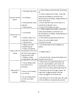
Page 27: ...ed Properly 1 Check and Correct fuse installation on the battery Test with Auxiliary Power Cable Check LCD Voltmeter with Battery under load and disconnected from Charger Charge Battery 24 hours and recheck 2 Defective Winch Motor 2 Replace Winch Motor 3 Damaged Forward Reverse Switch 3 CU needs to be sent in to replace switch Depth Counter Not Accurate 1 Cable Slippage on Roller 1 Ensure cable is...

Page 28: ...rnal Issue 3 Send CU to Laval Battery will not Charge 1 Battery Fuse Not Installed Properly 1 Check and Correct fuse installation on battery 2 Battery Completely Dissipated should not be left without charging for long periods of time 2 Replace Battery 3 Battery is being Charged while under load 3 Disconnect from Load and allow battery to charge for 12 24 hours Video will not Playback 1 Cannot Repl...

Page 29: ...by the manufacturer thereof No other warranties expressed or implied of merchantability fitness for a particular purpose or otherwise are made by LAVAL UNDERGROUND SURVEYS other than those set out in the immediately preceding paragraphs All repairs shall be made by LAVAL UNDERGROUND SURVEYS at its factory or as otherwise authorized by LAVAL UNDERGROUND SURVEYS in writing All unauthorized repairs w...

Reviews: