2
Connecting the Camera
1.
Turn the SPEED Dial (Figure 4 Item 4) all the way to MIN.
2.
Place the REEL CONTROL Power Switch on the Control Unit in the ON position (Figure 4
Item 1).
3.
Flip the Reel Control FORWARD-STOP-REVERSE Switch (Figure 4 Item 3) to the
FORWARD position and turn the SPEED Dial (Figure 4 Item 4) slowly towards the MAX.
4.
Run out enough cable so that the Camera (Figure 1 Item 6) when connected is centered
above the hole.
5.
Position the REEL CONTROL Power Switch to OFF (Figure 4 Item 1).
6.
Before connecting the Camera to the Cable head (Figure 3 Item 1) inspect the O-rings in
both connectors to be sure they are clear of debris or any contamination. Also check for
any wear or damage. The O-rings should also be re-lubricated on a regular basis. Use a
NEMA-rated O-rings lubricant.
7.
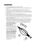
Slide the Centering Band Assy (Figure 3 Item 2) and Upper Support Tube (Figure 3 Item
3) beveled end first, over and past the Cable head (Figure 3 Item 1). Connect the Twist
Locking Cable head Connector to the Camera by carefully aligning the keyway on the
connectors together and twisting the lock until seated.
The cable head connector
should only be hand tightened.
Never over tighten the connectors
or upper support tube.
8.
Thread the Upper Support Tube to
the top of the Camera. Position the
Lower Centering Band Collar on the
Camera Housing (Figure 3 Item 4) at
least ½”
above the Side View Port
(Figure 3 Item 5).
DO NOT ATTACH
THE CENTERING BAND COLLAR TO
WITHIN ½” OF THE GLA
SS PORT
.
Position the Upper Collar on the
Upper Support Tube so that the
Centering Bands are extended to
approximately ½ inch less than the
diameter of the well or borehole
being inspected.
1
0
3
4
0
5
0
Figure 3
2
0

