12
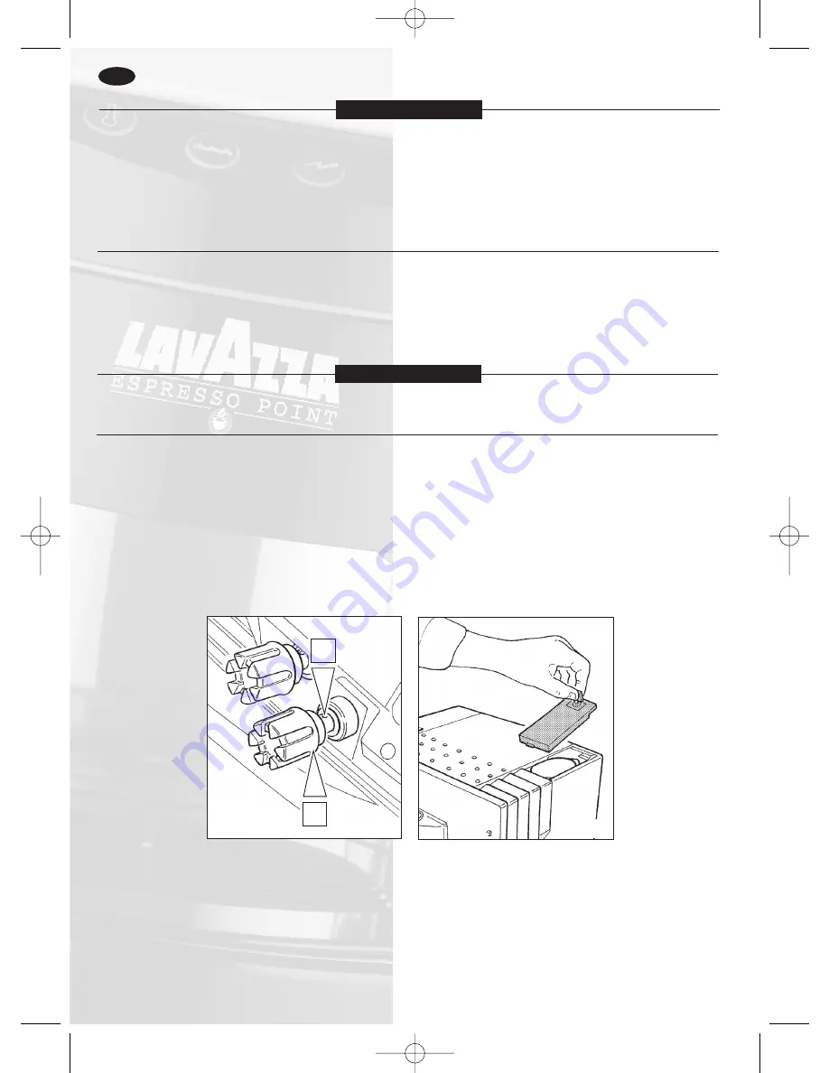
We recommend the use of stripped cable of a suitable diameter: unscrew the clamps
(fig. 4, A). Insert the cable in the hole provided (fig. 4, B) and wind it around the pin,
then fasten it in place by screwing the clamp back into position. The use of “banana”
connectors, whilst possible, is inadvisable for stable contact if the machine is subject to
vibrations.
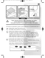
Remove the right-hand access cover using the key (fig. 5).
Fig. 4
Fig. 5
B
A
GB
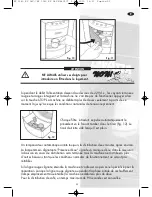
Unhook the central cover (fig. 6), extract the tank (fig. 7) and fill it with drinking water,
soft water if possible.
Move the switch on the back of the machine to the “I” position (fig. 8).
Connect the clamps to the power cables making sure that the positive pole if connected
to the red pin marked with a (+) and that the negative pole is connected to the black pin
marked with a (-).
WARNING
It is necessary to remove the adhesive feet for the assemblage of the
kit of sliding support; the apparatus must be placed in order
to make the clamps (red and black plugs) accessible.
Inadequate tightening of the support or the runners may leave the machine
unstable if installed in a moving vehicle.
WARNING
If the power poles are exchanged the machine will not work.
EP 2140 EP 24V:“EP 2140 EP 24V M44010” 9-03-2010 18:57 Pagina 12


