DVR User Manual
Page 1: ...DVR User Manual...
Page 2: ...y kind on this device Do not put any other equipment on top of this device Do not attempt to repair this DVR yourself please refer all repair to a qualified technician Only use a Hard Disk Drive speci...
Page 3: ...nu ICONs 17 3 9 LIVE VIEW 18 3 10 RIGHT BUTTON MeNU 19 3 11 MAIN MENU INTRODUCTION 23 3 12 main menu the SEARCH menu 24 3 13 main menu the CONFIGURATION menu 27 3 14 MAIN menu the STORAGE menu 44 3 15...
Page 4: ...5 4 Pan Tilt Zoom 79 5 5 Voice Intercom 84 5 6 Hard Disk redundancy 84 5 7 HDD S M A R T 85 5 8 dvr firmware update 87 5 9 TERMS 88 5 10 HDD CAPACITY CALCULATION 89 5 11 Common Faults 92 Appendix1 Re...
Page 5: ...pports D1 30 fps resolution RECORDING Recording modes include manual timed alarm and motion detection It supports SATA hard disks and local disk S M A R T technology This DVR also supports USB backup...
Page 6: ...You can control the system using the front panel and the supplied remote control or mouse 3 3 INSTALLATION 3 3 1 CHECK DVR AND ACCESSORIES When you unpack the DVR you should find the following items...
Page 7: ...he mounting holes in the bottom of the DVR Orient the drive so that the power and data cable connectors are facing the front of the DVR and align the mounting holes on the hard disk with the mounting...
Page 8: ...you will need to do the following Place the DVR on a flat stable surface and connect the cameras to the video input jacks on the back panel Connect the VGA video output port to the system display moni...
Page 9: ...Function Keys Function keys and the corresponding number key to switch or exit the function keys 5 Directional keys Directional controls Up Down can jump up or down Activates the digital input box to...
Page 10: ...gital input box to increase or decrease a number Left Right Switches screens Enter Operation confirmation Switches to default button Menu configuration 4 Function Keys Function keys and the correspond...
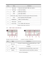
Page 11: ...RJ45 network cable connector USB Ports USB 2 0 Ports for mouse external device NOTE The bottom USB port is not available 5 VGA VGA output port 6 Power input DC 12V 7 RS 485 Port A B RS 485 port for P...
Page 12: ...at the A and B ports to reduce signal interference when there are several P T Z decoders connected Rear Panel Instruction for 8 16CH 1U case Rear Panel Instruction for 4 8 16CH 1U case DIAGRAM 3 2 RE...
Page 13: ...SB Network USB2 0 and RJ 45 interface 8 Power input DC 12V 9 Power switch Turn on off the DVR main power FORM 3 2 RARE PANEL FUNCTION 3 4 3 RARE PANEL I O INTERFACE DIAGRAM 3 33 8CH I O INTERFACE DIAG...
Page 14: ...wn list will pop up Under 3D P T Z control mode click the mouse and drag to the lower right this will enable 3D P T Z control Drag from the lower right to upper left to make 3D P T Z control narrow Fo...
Page 15: ...s symbols or uppercase and lowercase letters Click the left mouse button to select value back arrow means backspace and the is used to enter a space Letter Input Interface DIAGRAM 3 5 LETTER INPUT INT...
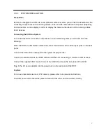
Page 16: ...ds After detection the DVR will sound an alarm and enter into multi screen live view which enables the user to start operation Please refer to the Main Menu Introduction or relevant instructions The R...
Page 17: ...the power switch if you plan to exchange the internal hard disk 3 7 3 OUTAGE RECOVERY If you have to reboot after a power outage or forced shutdown the DVR will have saved any files before the power...
Page 18: ...ected Drop down menu Confirm changes Enter a menu Cancel changes Cancel entering a menu Set parameters Save parameters Restores factory default settings or reverts to the last set of saved parameters...
Page 19: ...tch display screens by using the DVR front panel the remote control or the USB mouse When enabling on screen messages for any external alarms video loss masking motion detection or network and IP conf...
Page 20: ...AM 3 11 RIGHT BUTTON MENU for both 4 8 channel DVR operation 3 10 1 SCREEN SWITCHING A maximum of eight channels can be displayed on one monitor screen The operator can choose to display one four or e...
Page 21: ...option will automatically switch the color configuration at a set time Make sure to check each box to enable this function Hue adjust the screen image color Brightness Adjust the screen image brightne...
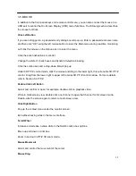
Page 22: ...a common recording when the Manual button is pressed Stop Stops all channel recording To change the record status of one channel first check if the recording status of the channel is selected or not n...
Page 23: ...3456 User user 123456 Hidden default default FORM 3 2 DEFAULT USERS Note Password security An alarm will occur if a password is entered incorrectly three times and there will be a system lockout for 3...
Page 24: ...management settings Storage Hard disk and back up management Output Configure out P T Z alarm output serial and output modes Maintenance Display the system log information version information stream...
Page 25: ...12 MAIN MENU THE SEARCH MENU You can call up the SEARCH interface through the Main Menu as shown in Diagram 3 16 Record Search DIAGRAM 3 16 RECORD SEARCH for both 4 8 channel DVR operation 1 5 2 3 4 9...
Page 26: ...oose to play the previous or next file choose to play the previous or next channel 7 List Choose the start time channel click search and a list will display the results 8 Backup Click to choose a back...
Page 27: ...pause can also switch to normal speed from slow motion playback Backward Backward Key Moves the video playback a single frame backward To go backwards single click again To stop backward play during...
Page 28: ...ss to several additional menus including System Record Network Alarm Account and Abnormity As shown in Diagram 3 17 Configuration below DIAGRAM 3 17 CONFIGURATION 3 13 1 CONFIGURATION MENU THE SYSTEM...
Page 29: ...top recording If you select Overwrite the DVR will overwrite the earliest recorded files and continue recording as if all HDD files are empty If you select the Stop recording option the DVR will stop...
Page 30: ...frame rate scope is different depending on each channel and resolution The Minor Stream supports either CIF or QCIF Main Stream parameters are selectable Frame Rate FPS PAL 1fps 25fps NTSC 1fps 30fps...
Page 31: ...sub menu below with additional configuration options DIAGRAM 3 20 MORE CONFIGURATIONS Channel Name Display Toggles on screen display of the channel name Date Display Toggles on screen date display Not...
Page 32: ...The video feed displays and you can use the cursor to resize the box displayed Preview Sets the masking zone masking zone is shown on the screen when displayed There is no masking zone in the web inte...
Page 33: ...guration to another Set Pops up the setting interface for one of the listed weekdays Diagram 3 22 Edit Plan DIAGRAM 3 22 EDIT PLAN Record Type Sets the recording time segments There are up to six conf...
Page 34: ...IP address assigned by the server The assigned dynamic IP address displays in the IP Address field You can manually enter a static IP address in the IP Address field if there is no DHCP service avail...
Page 35: ...tain a public IP address from your ISP You can then access the DVR s web interface by typing that IP address into Internet Explorer or some other browser DDNS Enables the DVR to update a DDNS hostname...
Page 36: ...following settings Max Connection 0 10 0 indicates that no connections are allowed Network connection NUM Selection options are from 0 32 You need to select it first then browse the real time video on...
Page 37: ...y IP time and channel if there is no remote folder specified FTP username and password Set a maximum file size channel time type and etc Set FTP file length Upload the whole recording if the file leng...
Page 38: ...t functional Detect Tab Settings Detect tab interface Diagram 3 25 Alarm Configurations DIAGRAM 3 25 ALARM CONFIGURATIONS Motion Detection Motion detection and alarm Set Area PAL 22 18 396 NTSC 22 15...
Page 39: ...6 different period times that the alarm is to be activated check the box and then select the times from and to the alarm should be activated selecting 00 00 to 24 00 will set the alarm to run continu...
Page 40: ...instead of continuous recording DIAGRAM 3 28 ALARM CONFIGURATION LOCAL ALARM PROCESS MODE ABNORMITY Process enables or disables the alarm method to be used Alarm Out does not function with 4 8 channel...
Page 41: ...nd User names cannot be duplicated and a User can only belong to one group The Account menu User management interface is shown in Diagram 3 29 User Management DIAGRAM 3 29 USER MANAGEMENT Add User Add...
Page 42: ...nformation alarm in out settings system configuration search log log delete upgrade operation authority etc Modify group Modifies existing Group information Modify Password Changes passwords To change...
Page 43: ...30 ABNORMALITY DIAGRAM 3 30 ABNORMALITY There are five items in the Abnormality menu To activate a warning or error message function click on the check box beside it The Process button beside each ite...
Page 44: ...utton accesses the same items as the one for No Disk Net Disconnection Displays a warning when a network is not connected The Process button access Alarm Output Show Message Send Email and Record Chan...
Page 45: ...give access to some disk management functions Maintains and manages the DVR s internal hard disk DIAGRAM 3 31 STORAGE MANAGEMENT Base Configuration HDD Base as shown in Diagram 3 32 HDD management bas...
Page 46: ...tions are read write read only or redundancy mode with check boxes to enable or disable each mode In read only mode video data cannot be recovered The sub menu also displays a variety of drive status...
Page 47: ...46 DIAGRAM 3 34 HDD MANAGEMENT RECORD...
Page 48: ...ke motion detect Video Loss Camera Masking as example to show you how to use cloud storage step by step DIAGRAM 3 35 CONFIGURATION INTERFACE Motion Detect Upload the snapshot on cloud storage Step 1 E...
Page 49: ...ALARM Step 3 Enter Detect tab to choose channel check Motion Detect checkbox and then click Process button on the right DIAGRAM 3 38 DETECT Step 4 Enter Process interface to set period linkage set pr...
Page 50: ...49 DIAGRAM 3 39 PERIOD DIAGRAM 3 40 LINKAGE SET DIAGRAM 3 41 PROCESS...
Page 51: ...tect to finish the configuration Connect Drop box Step 1 select Drop box Click Bind DIAGRAM 3 42 CLOUD STORAGE Step 2 open the linking via you browser scan QR code with your Ipad phone DIAGRAM 3 43 BI...
Page 52: ...dropbox com to apply for an account DIAGRAM 3 44 DROP BOX SIGN IN Step 4 Authorized the specific DVR to visit your drop box and get the authorization code DIAGRAM 3 45 DROP BOX AUTHORIZATION Step 5 En...
Page 53: ...52 DIAGRAM 3 46 ENTER AUTHORIZATION CODE DIAGRAM 3 47 DROP BOX CAPACITY...
Page 54: ...automatically Then you can login drop box and get the information you want www dropbox com DIAGRAM 3 49 LOGIN DROP BOX DIAGRAM 3 50 CHECK INFORMATION 3 14 3 STORAGE MENU THE BACKUP MENU Connect an Ext...
Page 55: ...ackup to enter the Backup menu see Diagram 3 52 Backup DIAGRAM 3 52 BACKUP Select the recording s Start and End times and click Add to add it to the list Duplicate it by inputting the Start and End ti...
Page 56: ...y which control management of peripherals connected to the DVR system Diagram shows the Output menu interface DIAGRAM 3 53 PERIPHERAL MANAGEMENT 3 15 1 OUTPUT MENU P T Z CONFIGURATION Set the Pan Tilt...
Page 57: ...a address The default is 1 Note This address has to correspond with the camera address or the cameras will not work Baud Rate Selects the camera s baud rate and control the default is 9600 Data Bits D...
Page 58: ...by net port P T Z matrix Controls the PTZ matrix Note Some models come without an RS 232 port please check your model s specifications Baud Rate Sets baud rate Data Bit Default 8 Stop Bit Default 1 Co...
Page 59: ...to 48 half width characters 2 Limit to 16 characters otherwise some problems may occur in multi screen mode Time Display Selects whether the time is displayed on screen Channel Display Selects whethe...
Page 60: ...ions TV Adjust Adjust the display output area It adjusts the image to the fit the display VGA TV Color Settings Adjust the display s hue brightness contrasts and saturation settings TV Color Settings...
Page 61: ...or single four or eight screen options Motion Tour Sets up motion detection based tour mode Alarm Tour Sets up the alarm based tour mode Note Setting shortcut click the button at the upper right hand...
Page 62: ...isplays system log information DIAGRAM 3 61 LOG To view log entries select the log type and desired time segment and then press the Find button The system will display the log in tab form You can also...
Page 63: ...e could cause a startup failure Only perform a firmware upgrade if you are sure you know what you are doing or under professional supervision 3 16 3 MAINTENANCE MENU THE DEFAULTS MENU The Defaults men...
Page 64: ...pecified reset all cameras and auto deletion of old files will delete files that reach the time limitation that is preset 3 16 6 MAINTENANCE MENU THE ON LINE USERS MENU ONLINE USERS Displays which Use...
Page 65: ...ings earlier in this manual Ensure that the IP address is correct and check whether the DVR is on the network Active x CONTROL SETUP LOG IN LOG Out Using the DVR s network information a User can remot...
Page 66: ...65 Diagram 4 1 login screen Click Install the re open the browser the following tips will shown as below Click the Yes button to access the DVR 4 1 2 WEB OPERATION INTERFACE...
Page 67: ...on 2 Function key Local playback playback local recording Open all play live views in surveillance window 3 Surveillance window Change window layout 4 Image color other saturation Image color modify b...
Page 68: ...m or secondary stream It also displays the current DVR s IP address and transfer rate as shown in Diagram 4 3 Stream information DIAGRAM 4 3 STREAM INFORMATION The lower left corner shows the current...
Page 69: ...urns audio on or off Video Off Turns off the focus window DIAGRAM 4 4 FUNCTION ICONS 4 1 4 P T Z CONTROL Set the P T Z protocol see Setting P T Z Configuration earlier in this manual Control a P T Z c...
Page 70: ...en click Add to save Auto Tour Operation Select Tour Point between the first cruise line and cruise input box value Input numbers in Path and Preset Click Add Preset to add a preset value to the cruis...
Page 71: ...ocal configuration menu by clicking on Configuration For further details please refer to Local operation guide Diagram 4 6 CONFIGURATION DIAGRAM 4 6 CONFIGURATION 4 1 6 SEARCH RECORD Click Search to o...
Page 72: ...played Play Double click a search result to play it in the video window Control the video playback by using the control icons A set of standard video playback control icons will display at the bottom...
Page 73: ...etection hard disk full hard disk failure video block video encoder alarm pop up Click on Prompt open the prompts When an alarm occurs in real time it pops up an alarm window menu Click on the Sound P...
Page 74: ...in name analysis server embedded in this DVR Please contact your dealer or agent for a DDNS account number Click enable in the configuration window after getting the account number and input the accou...
Page 75: ...reate a domain name and click on Add a Host DVR Setting Open Main Menu Configuration Network Advanced DDNS Enable Item Configuration DDNS NO IP DDNS IP dynupdate no ip com Port 80 Domain name xxx xxx...
Page 76: ...d xxxxxx 5 1 6 TEST AND VERIFY DDNS After configuring the Embedded DVR wait for a few minutes to allow the analysis records to update Click on Operation in the menu input cmd and click OK to open a co...
Page 77: ...n a user connects to the port of the IP address the server will automatically map the request to the corresponding machine on the LAN With the port mapping function we can map many ports of one machin...
Page 78: ...connect to the IP address or static IP After setting up the IP address click the Advanced Configuration and navigate to the menu with ports and multicast etc Enable UPnP port mapping The third step En...
Page 79: ...ION The NTP function handles time synchronization between the DVR and the GPS clock server to ensure the accuracy of both devices 5 3 1 INTERNET CONFIGURATION Go to CONFIGURATION NETWORK select Advanc...
Page 80: ...above It is best to always make a backup of your registry before attempting any changes NTP Server Set Up Under Linux Due to the differences between Linux distributions for details on how to set up a...
Page 81: ...ns drag from top left to bottom right to zoom in drag from bottom right to top left for zoom out Advanced Functions Click Page Switch to switch to the advanced functions as shown in Diagram 5 4 P T Z...
Page 82: ...d functions Diagram 5 6 Preset setting DIAGRAM 5 6 PRESET SETTING Preset Diagram 5 6 Preset setting it sets up camera positions using the directional keys Click Preset and input a Preset number then c...
Page 83: ...as Pattern X a number click on Begin go back to the P T Z control menu to modify the Zoom Focus and Iris settings etc then back to the menu below to End DIAGRAM 5 8 PATTERN Border setting Click Border...
Page 84: ...it Menu access or quit the camera settings menu Click Page Switch to get back to interface as shown in Diagram 5 3 P T Z control The directional key is mainly used for internal menu control i e the ca...
Page 85: ...e 5 6 HARD DISK REDUNDANCY The hard disk drive HDD redundancy function can backup recorded files The User can then retrieve files from a redundant HDD if a single HDD is damaged This enhanced system d...
Page 86: ...e security situation Detection parameters for a Seagate HDD for example are divided into seven parts ID detection code Attribute Description Threshold Attribute Value Worst Date and Status 1 ID Detect...
Page 87: ...m attribute value is 100 for IBM Quantum and Fujitsu or 253 for Samsung Of course there are some exceptions for example some models produced by Western Digital have two different attribute values and...
Page 88: ...downloaded update file 1 Uncompress the DVR update file e g DeviceUpdate_V1 10 R 20120822 rar 2 Double click the DVR network update tool RECUpgrade exe as below 3 Enter the IP address and TCP port cod...
Page 89: ...pdatepacket bin file to vss bin put it into the root directory of a USB drive then plug the USB drive into the USB port on the DVR Using the DVR s OSD interface go to Main Menu Maintenance Version and...
Page 90: ...echnology Now widely used in hard disk data security technology a monitoring system analyzes motor circuit HDD and disk head when a HDD is running and warns you when there is an abnormality CVBS Compo...
Page 91: ...File 96k 42M 320k 140M 896k 393M 128k 56M 384k 168M 1 00M 450M 160k 70M 448k 196M 1 25M 562M 192k 84M 512k 225M 1 50M 675M 224k 98M 640k 281M 1 75M 787M 256k 112M 768k 337M 2 00M 900M FORM5 1 RECORD...
Page 92: ...s hard disk are suitable too How To Detect Western Digital HDDs a Go to www wdc com choose WD support download SATA SAS WD Caviar GP then download the software as shown in Diagram 5 112 WD Download D...
Page 93: ...ard please contact your supplier 3 There is an HDD error Replace the faulty HDD Remote control does not work Possible reasons 1 Check if the batteries in the remote control are installed properly 2 Ch...
Page 94: ...standard the preview will be blurred Blurred screen in playback mode or failure to play back recordings Possible reasons 1 Procedure error reboot the DVR 2 HDD error test or replace the HDD 3 DVR har...
Page 95: ...the Tools menu and go to the Advanced tab Make sure the memory protection item is not enabled See the following DIAGRAM 5 14 IE TOOL BAR Internet Explorer 9 0 or above Please use a compatible mode if...
Page 96: ...ht and Enter Menu button 5 Record Playback control Control recording playback 6 Record mode Enter short menu as record mode button 7 ADD Input the number of DVR to control 8 FN Assistant function 9 Se...