Superabrasive
User Manual
Original Language
Lavina® 25-X
9/2018
27
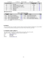
**for machines with serial No1711L25X2161 and bigger
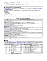
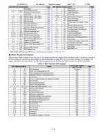
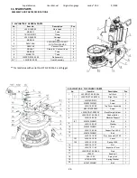
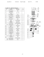
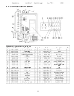
3. LAVINA®25-X TOP COVER PARTS 2
No.
Item No.
Description
Pcs.
1
L25X-19.00.01
Top Cover
1
2
L25GS-19.10.00
Vacuum Port
1
3
L25X-19.20.00
Water Fitting
1
4
M12DIN985
Nut
1
5
M5DIN125A
Washer
4
6
M5DIN127B
Spring Washer
4
7
M5DIN934
Nut
4
8
L25SPS-04.01.00.00
Vacuum Port
1
9
M5X16DIN84A
Screw
3
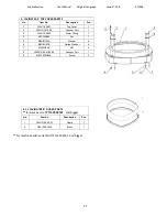
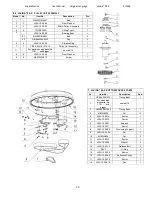
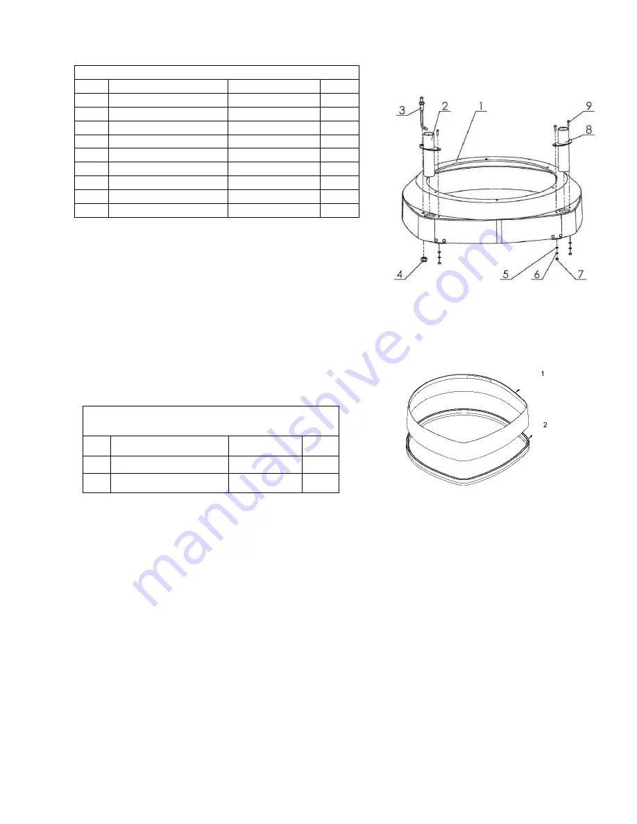
4.1.1 LAVINA®
25-X
GUARD PARTS
**
for machines No
1711L25X2161
and bigger
No.
Item No.
Description
Pcs.
1
L25GX-05.00.01
Guard
1
2
FBL1350-2240
Brush
1


