The Rear Panel
8
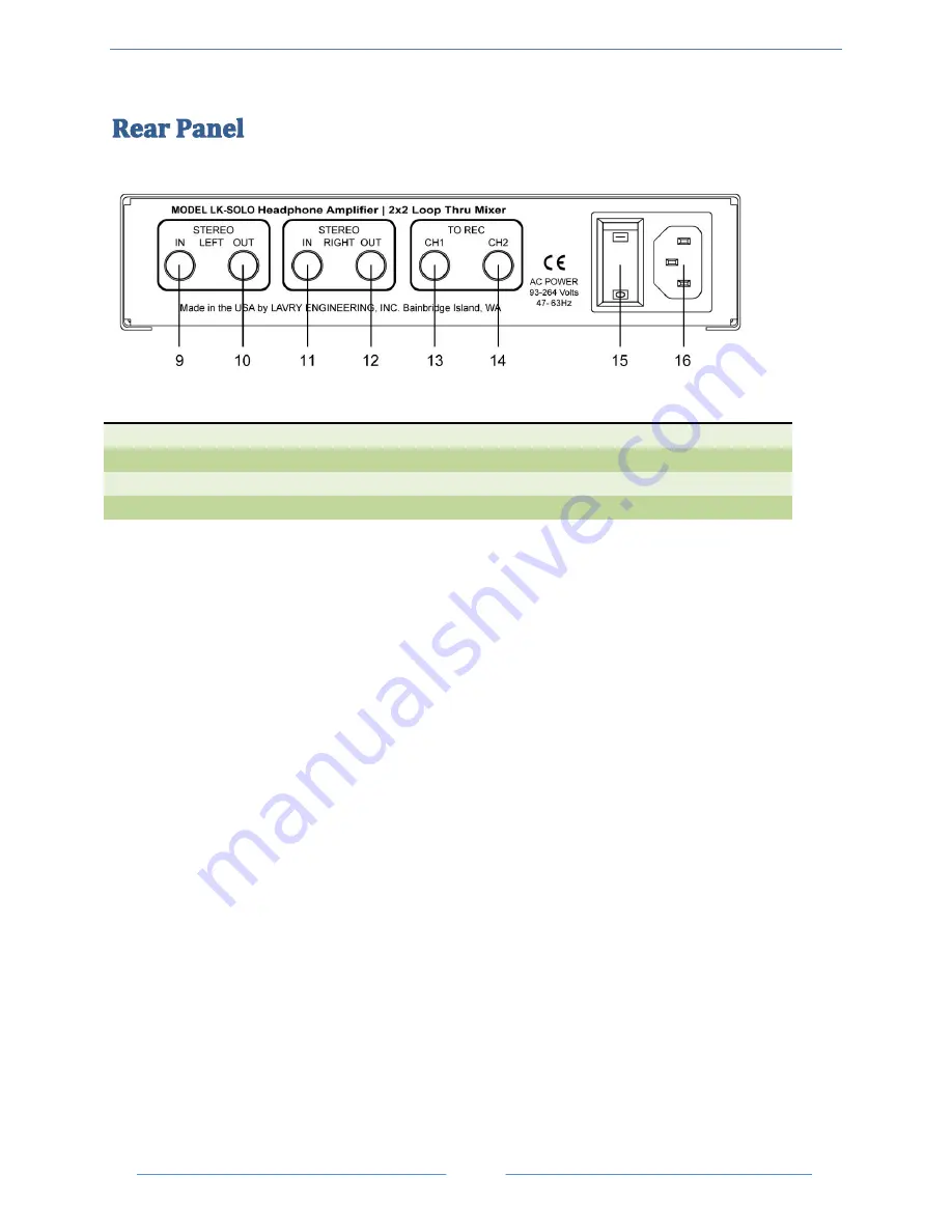
Figure 3- Rear Panel Layout
9. Stereo Input Left
10. Stereo Output Left
11. Stereo Input Right
12. Stereo Output Right
13. CH1 Output
14. CH2 Output
15. Power Switch
16. AC Power Connector
S
TEREO
I
NPUT
L
EFT
This ¼” input receives the left analog output of the DAW or of any stereo source.
S
TEREO
O
UTPUT
L
EFT
This ¼” output is hardwired to
Stereo Input Left
, allowing an unbroken connection from the left analog
output of the DAW to the destination (i.e. monitor controller, mixer, etc.).
S
TEREO
I
NPUT
R
IGHT
This ¼” input receives the right analog output of the DAW or of any stereo source.
S
TEREO
O
UTPUT
R
IGHT
This ¼” output is hardwired to
Stereo Input Right
, allowing an unbroken connection from the right analog
output of the DAW to the destination (i.e. monitor controller, mixer, etc.).
CH1
O
UTPUT
This ¼” output is hardwired to the
CH1/Mono Input
on the front panel, allowing an unbroken connection
from the CH1 /Mono Source to the analog input of the DAW.
CH2
O
UTPUT
This ¼” output is hardwired to the
CH2 Input
on the front panel, allowing an unbroken connection from the
CH2 source to the analog input of the DAW.
P
OWER
S
WITCH
The power switch is a two position rocker switch.
AC
P
OWER
C
ONNECTOR
This unit accepts AC Power in the range of 93-264 Volts at 47-63 Hertz. Adjustment to AC power input
in this range is automatic; there are no settings to change.

