12
ASSEMBLY
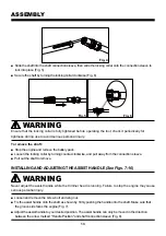
FITTING THE DEBRIS GUARD
(See Figs. 1-3)
■ Loosen and remove the screw from the debris guard using the screwdriver provided.
■ Starting from the top of the split shaft, slide the debris guard all the way down to the correct mounting
position as shown (Fig. 1).
■ Align the screw hole on the debris guard with the screw hole on the bracket. Insert the screw through the
debris guard and the bracket on the shaft (Fig. 2).
■ Secure the screw tight using the screwdrive (Fig. 3).
INSTALLING AND REMOVING THE SHAFT
(See Figs. 4-6)
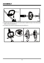
To install the shaft:
■ Turn the locking collar counter-clockwise to remove it from the shaft connection sleeve. Slide the locking
collar onto the shaft.
■ Check to ensure the axles in the shafts are aligned as shown (Fig. 4). If not aligned, slightly rotate the
trimmer head to adjust the axle until it aligns.
WARNING
The trimming line cutting blade on the debris guard is sharp and is fitted with a blade protection film
which will need to be removed prior to using the trimmer. When fitting the guard avoid contact with
the blade. Failure to avoid contact can result in serious personal injury.
WARNING
Never install, remove, or adjust any attachment while the engine is running. Failure to stop the engine
can cause serious personal injury.
Fig. 1
Fig. 2
Fig. 3
Hole on the
debris guard
Hole on the
bracket
Summary of Contents for NPTGCP2517B
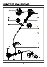
Page 9: ...9 KNOW YOUR GRASS TRIMMER 1 2 3 4 5 6 7 8 9 10 11 12 13 14 15 16 17 18 19 20 21 22 23 24 25...
Page 38: ...38 EXPLODED VIEW NPTGCP2517B EXPLODED VIEW...
Page 40: ...40 EXPLODED VIEW 25CC 2 CYCLE ENGINE...
Page 42: ...42 NOTES...
Page 43: ...43 NOTES...
Page 51: ...51 CONOZCA SU BORDEADORA 1 2 3 4 5 6 7 8 9 10 11 12 13 14 15 16 17 18 19 20 21 22 23 24 25...
Page 80: ...80 VISTA EXPANDIDA NPTGCP2517B VISTA EXPANDIDA...
Page 82: ...82 VISTA EXPANDIDA DEL MOTOR DE 2 TIEMPOS DE 25 CC...
Page 84: ...84 NOTAS...
Page 85: ...85 NOTAS...


