background image

69

MANTENIMIENTO

MANTENIMIENTO DE LA BATERÍA

■  Almacene la batería hasta que esté cargada por completo.
■  No deje que la batería se descargue por completo.
■  Una vez que la batería esté completamente cargada, desconecte el cargador de la toma de 

corriente y saque la batería del cargador. 

■  No almacene la batería puesta en la herramienta o en el cargador.
■  Cargue la batería a una temperatura entre 40 °F (4 °C) y 100 °F (38 °C). Si la batería está caliente, 

deje que se enfríe antes de cargarla.

Para almacenar la batería durante 30 días o más:

Si la batería de iones de litio se almacenará durante 30 días o más, almacénela en un lugar libre de 
humedad donde la temperatura no sobrepase los 26 °C (80 °F).
-  Almacene la batería con una carga de 30 % a 50 %.
-  Cargue la batería por completo cada seis meses.
-  La parte exterior de la batería puede limpiarse con un paño o cepillo suave no metálico.

MANTENIMIENTO DEL CARGADOR

■  Mantenga el cargador limpio y libre de sedimentos. No deje que materiales extraños entren en 

la cavidad o en los contactos. Limpie con un paño seco. No use solventes, agua o exponga el 
dispositivo a condiciones húmedas.

■  Siempre desenchufe el cargador cuando la batería no esté dentro del cargador.
■  Mantenga el cargador almacenado a temperatura ambiente normal. No almacene el cargador bajo 

un calor excesivo. No utilizar bajo luz solar directa.

■  Desconecte el cargador de la toma de corriente eléctrica cuando no esté en uso y cuando la batería 

se haya cargado por completo. 

CAMBIO DEL CARRETE 

(Consulte las Figuras 29-32)

■  Detenga el motor y extraiga la batería.  
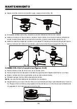
■  Sostenga la cubierta principal del carrete y gire el cabezal del carrete hacia la izquierda para 

sacarlo. Luego, saque de la bordeadora la cubierta principal del carrete junto con el carrete (Fig. 29).


Fig. 29

Summary of Contents for NPTGCP2517B

Page 1: ...instrucciones de seguridad antes de utilizar esta herramienta 601 Regent Park Court Greenville SC 29607 SC 29650 1 866 384 8432 NOTICE Only use unleaded gasoline containing up to 10 ethanol Do not us...

Page 2: ...2 3 6 7 8 9 10 11 15 16 17 18 25 26 33 34 35 36 37 38 39 40 41 42 43 Engine Type Engine Displacement Claimed Rated Power Speed Idle Speed Max Torque Speed Fuel Tank Capacity Fuel Oil Ratio Line Diamet...

Page 3: ...zone there is still a risk of injury from thrown objects Bystanders should be encouraged to wear eye protection If you are approached stop the engine and cutting attachment Always wear eye protection...

Page 4: ...stopping the engine and letting it cool completely Do not smoke while fueling or mixing fuel Wipe spilled fuel from the trimmer Move at least 10 ft 3 m away from the fueling source and the site before...

Page 5: ...ure above 265 F 130 C may cause an explosion Do not modify or attempt to repair the battery pack as applicable except as indicated in the instructions for use and care Follow all charging instructions...

Page 6: ...rference to radio communications However there is no guarantee that interference will not occur in a particular installation If this equipment does cause harmful interference to radio or television re...

Page 7: ...ring protection when operating this equipment Precaution that involves your safety Gloves Wear non slip heavy duty protective gloves when handling this product Safety Footwear Wear non slip safety foo...

Page 8: ...garding available recycling and or disposal options SYMBOL SIGNAL MEANING DANGER Indicates an imminently hazardous situation which if not avoided will result in death or serious injury WARNING Indicat...

Page 9: ...9 KNOW YOUR GRASS TRIMMER 1 2 3 4 5 6 7 8 9 10 11 12 13 14 15 16 17 18 19 20 21 22 23 24 25...

Page 10: ...ndicator 18 Throttle Safety 19 Engine Housing 20 Spark Pulg Cap 21 Start Button Cover 22 Trimmer Line Cutting Blade 23 Shaft Connection Sleeve 24 Throttle Lever 25 Muffler 26 Charging Port 27 Battery...

Page 11: ...bling parts This product requires assembly Carefully remove the product and any accessories from the box Make sure that all items listed in the packing list are included Inspect the product carefully...

Page 12: ...ollar counter clockwise to remove it from the shaft connection sleeve Slide the locking collar onto the shaft Check to ensure the axles in the shafts are aligned as shown Fig 4 If not aligned slightly...

Page 13: ...shaft by turning the locking collar clockwise Fig 6 ASSEMBLY WARNING Ensure that the locking collar is fully tightened before operating the tool check it periodically for tightness during use to avoid...

Page 14: ...he screw holes on the assist handle and tighten the wing nut Secure the wing nut tightly by turning it clockwise Fig 9 Pay attention not to position the assist handle under the shaft Fig 10 Handle Pos...

Page 15: ...he battery slot until the battery pack secures into place Make sure the battery is inserted in the correct direction Fig 11 Do not use force when inserting the battery pack It should slide into positi...

Page 16: ...fect the battery CHARGER LEDS If the battery is not connected to the charger a continuous green LED light indicates that the plug is plugged into an outlet socket and the battery charger is ready for...

Page 17: ...ecifications and then disconnect the charger from the power supply Remove the charging connector from the charging port Fig 14 NOTE It is normal for the battery pack and the charger to become warm but...

Page 18: ...s personal injury Before each use inspect the entire product for damaged missing or loose parts such as screws nuts bolts caps etc Tighten securely all fasteners and caps and do not operate this produ...

Page 19: ...out the United States contains ethanol The maximum ethanol content allowed by law for use in outdoor power equipment is limited to 10 E10 Most small power equipment engines are designed to use no more...

Page 20: ...and inspecting the tank Check that the cap is sealed tightly and wipe clean any spillage that may have occurred NOTICE It is normal for smoke to be emitted from a new engine after first use WARNING T...

Page 21: ...m up at idle for at least 1 minute or lightly engage the throttle to speed up the process Engaging the throttle fully before the trimmer is warm can cause the engine to stall Fig 18 20 To begin trimmi...

Page 22: ...d the throttle lever to start the trimmer To stop the trimmer Press the STOP switch to the stop position O until the trimmer stops Fig 23 STOP BATTERY POWER INDICATOR See Fig 24 A battery power indica...

Page 23: ...osition with the rear handle at waist level Fig 25 WARNING The engine housing can become hot when the trimmer is being used Do not make contact with this part of the tool during use and whilst it is s...

Page 24: ...g 26 Use the tip of line to do the cutting do not force the trimmer head into uncut grass The line can wear quickly and even break when used against solid surfaces such as fences borders curbs and wal...

Page 25: ...CUTTING BLADE See Fig 28 The trimming line cutting blade is attached to the underside of the debris guard Fig 28 The cutting blade trims the line at a length that yields optimum cutting results If th...

Page 26: ...ety devices air vents and the motor housing free of dirt and dust Regularly clean the ventilation slot in your grass trimmer using a soft brush or dry cloth Regularly clean the cutting line and spool...

Page 27: ...y six months The exterior part of the battery pack may be cleaned with a cloth or soft non metallic brush CHARGER MAINTENANCE Keep the charger clean and clear of debris Do not allow foreign material i...

Page 28: ...e main spool cover and turn clockwise to secure it Fig 32 LINE REPLACEMENT See Figs 33 35 You may wind new cutting lines onto an empty spool Replacement cutting line is available from a DIY store or o...

Page 29: ...wear and replace parts if necessary Install the spool in the spool cover and replace as described in the Spool Replacement section NOTE Only use the appropriate cutting line specified in this manual T...

Page 30: ...Spark arrestors may be in different locations depending on the model purchased Please contact your nearest service dealer for the location of the spark arrestor for your model IDLE SPEED ADJUSTMENT T...

Page 31: ...nk cap if required A clogged fuel filter will cause poor engine percformance Replace the fuel filter if required as it is a non serviceable part Please contact your nearest service center for replacin...

Page 32: ...or replace with a new one DO NOT use a blowing tool to clean as the movement of dirt may damage the engine Adjust spark plug gap by bending outer electrode Fig 43 Reinstall the cleaned or a new spark...

Page 33: ...cordingly Operating the engine with the wrong engine configuration at a given altitude may increase its emissions drop fuel efficiency reduce performance and cause irreparable damage Engines configure...

Page 34: ...nd corrosive materials are in the batteries used in this battery pack Lithium ion a toxic material To avoid injury and risk of fire explosion or electric shock and to avoid damage to the environment C...

Page 35: ...fuel tank Push the primer bulb until the bulb is full of fuel If the bulb does not fill the primary fuel delivery system is blocked Contact an authorized service dealer If the primer bulb fills the en...

Page 36: ...The line will not advance The line is welded to itself Lubricate the line with silicone spray Insufficient cutting line Install more line Refer to the Line Replacement section in this manual The line...

Page 37: ...that has become inoperative due to alteration misuse commercial use abuse neglect accident or improper storage or maintenance 2 The unit if it has not been operated and or maintained in accordance wit...

Page 38: ...38 EXPLODED VIEW NPTGCP2517B EXPLODED VIEW...

Page 39: ...e body Set 1 2 2 321007104 Starter Set 1 2 2 1 321001105 Electric Switch 1 2 2 2 321007105 Starter Switch Assembly 1 2 2 3 321007106 Stop Switch Set 1 2 2 4 321007107 PCB Assembly 1 3 321007108 Connec...

Page 40: ...40 EXPLODED VIEW 25CC 2 CYCLE ENGINE...

Page 41: ...lation Sheet 1 6 321007188 Front Cover Assembly 1 7 321007189 Clutch Assembly 1 8 321007190 Connection Cover Assembly 1 9 321007191 Flywheel Assembly 1 10 321007149 Crankcase Assembly 1 11 321007192 P...

Page 42: ...42 NOTES...

Page 43: ...43 NOTES...

Page 44: ...7 58 64 65 67 68 75 76 77 78 79 80 81 82 83 84 85 Tipo de motor Desplazamiento del motor reportado nominal Potencia velocidad Velocidad en ralent Torque velocidad m xima Capacidad del tanque de combus...

Page 45: ...50 pies 15 m sigue habiendo riesgo de lesiones por los objetos que puedan salir expelidos Se debe insistir en que las personas cercanas usen protecci n ocular Si alguien se le acerca detenga el motor...

Page 46: ...do para el almacenamiento de gasolina Mezcle y vierta la gasolina en exteriores donde no haya chispas ni llamas Quite lentamente la tapa de combustible solo despu s de detener el motor y dejarlo enfri...

Page 47: ...s terminales puede provocar chispas quemaduras o incendios No exponga la bater a al fuego o temperaturas excesivas La exposici n al fuego o a temperaturas sobre los 265 F 130 C puede provocar una expl...

Page 48: ...equipo genera usa y puede irradiar energ a de radiofrecuencias y de no instalarse y usarse seg n las instrucciones puede provocar interferencias perjudiciales en las comunicaciones por radio Sin emba...

Page 49: ...do opera este equipo Precauci n que involucra su seguridad Guantes Al utilizar este producto utilice guantes de protecci n antideslizantes y de alta resistencia Calzado de seguridad Al utilizar este p...

Page 50: ...cuanto a las opciones leg timas para desechar o reciclarlas S MBOLO SE AL SIGNIFICADO PELIGRO Indica una situaci n peligrosa inminente la cual de no evitarse podr a causar la muerte o lesiones severas...

Page 51: ...51 CONOZCA SU BORDEADORA 1 2 3 4 5 6 7 8 9 10 11 12 13 14 15 16 17 18 19 20 21 22 23 24 25...

Page 52: ...n de encendido 17 Indicador de la bater a 18 Seguridad del acelerador 19 Carcasa del motor 20 Tap n de la buj a 21 Cubierta del bot n de encendido 22 Hoja de recorte del hilo de corte 23 Manga de con...

Page 53: ...to y sus accesorios de la caja Aseg rese de que todos los elementos mencionados en la lista de componentes del empaque est n incluidos Inspeccione el producto cuidadosamente para asegurarse de que no...

Page 54: ...Consulte las Figuras 4 6 Para instalar el eje Gire el collar n de bloqueo hacia la izquierda para sacarlo de la manga de conexi n del eje Deslice el collar n de bloqueo hacia el eje Revise que los ej...

Page 55: ...del eje y luego deslice el collar n de bloqueo hacia la manga de conexi n para fijarla en posici n Fig 5 Asegure el eje girando el collar n de bloqueo hacia la derecha Fig 6 MONTAJE ADVERTENCIA ADVERT...

Page 56: ...hacia la derecha Fig 9 Preste atenci n a no dejar la empu adura de apoyo bajo el eje Fig 10 Handle Position Fig 7 Fig 8 Ranura Fig 9 Fig 10 Ajuste la empu adura de apoyo a la posici n deseada La empu...

Page 57: ...bater a Inserte la bater a en la ranura de la bater a hasta que quede asegurada Aseg rese de insertar la bater a en la direcci n correcta Fig 11 No utilice fuerza al insertar la bater a Debe deslizar...

Page 58: ...e carga no afecta a la bater a LED DE CARGA Si la bater a no est conectada al cargador una luz LED verde continua indica que el enchufe est conectado en una toma de corriente y que el cargador est lis...

Page 59: ...as especificaciones del producto y desconecte el cargador de la toma de energ a Quite el conector de carga del puerto de carga de la bater a Fig 14 NOTA Es normal que la bater a y el cargador se calie...

Page 60: ...podr a causar lesiones severas Antes de cada uso inspeccione el producto completo en busca de piezas da adas faltantes o sueltas tales como tornillos tuercas tapas etc Apriete con seguridad todos los...

Page 61: ...que contiene 10 de etanol se puede utilizar de forma segura en sus productos de LawnMaster Gran parte de la gasolina comercializada en todos los Estados Unidos contiene etanol El contenido m ximo de...

Page 62: ...e despu s de llenarlo e inspeccione el tanque Revise que la tapa est bien sellada y limpie cualquier derrame que pueda haberse producido AVISO Es normal que un motor nuevo emita humo despu s de usarse...

Page 63: ...cionando en ralent durante al menos 1 minuto o active suavemente el acelerador para apresurar el proceso Activar el acelerador al m ximo antes de que la bordeadora se caliente puede provocar que el mo...

Page 64: ...ender la bordeadora Para detener la bordeadora Presione el interruptor de detenci n hacia la posici n O hasta que la bordeadora se detenga Fig 23 STOP INDICADOR DE POTENCIA DE LA BATER A Consulte las...

Page 65: ...e debe mantener en una posici n c moda con la empu adura trasera al nivel de la cintura Fig 25 ADVERTENCIA La carcasa del motor puede calentarse cuando la bordeadora est en uso No toque esta parte de...

Page 66: ...a del hilo para cortar no fuerce el cabezal hacia el pasto sin cortar El hilo puede gastarse r pidamente e incluso romperse cuando se usa contra superficies s lidas tales como rejas bordes fachadas y...

Page 67: ...hoja de recorte del hilo se encuentra en la parte inferior del protector contra sedimentos Fig 28 La hoja de recorte ajusta el largo de la l nea de manera tal que se logre el resultado de corte ptimo...

Page 68: ...Mantenga todos los dispositivos de seguridad ventilaciones de aire y la carcasa del motor libres de polvo y suciedad Limpie regularmente la ranura de ventilaci n de su bordeadora utilizando un cepillo...

Page 69: ...La parte exterior de la bater a puede limpiarse con un pa o o cepillo suave no met lico MANTENIMIENTO DEL CARGADOR Mantenga el cargador limpio y libre de sedimentos No deje que materiales extra os ent...

Page 70: ...cubierta y gire hacia la derecha para asegurarlo Fig 32 CAMBIO DEL HILO Consulte las Figuras 33 35 Puede enrollar un hilo de corte nuevo en un carrete vac o Puede comprar hilo de repuesto en tiendas...

Page 71: ...esario Instale el carrete en la tapa del carrete y reinst lelo siguiendo los pasos de la secci n Cambio del carrete NOTA use solo el hilo de corte especificado en este manual REINSTALACI N DEL CABEZAL...

Page 72: ...contra chispas pueden encontrarse en distintos lugares dependiendo del modelo adquirido Contacte a su centro de servicio m s cercano para averiguar d nde est el protector contra chispas de su modelo A...

Page 73: ...el rendimiento mejora al soltar el tap n del tanque de combustible la v lvula podr a estar defectuosa Reemplace el tap n del tanque de combustible si es necesario Un filtro de combustible tapado prov...

Page 74: ...Revise que la buj a no est gastada dentada o que el electrodo central no est redondeado Limpie la buj a o c mbiela por otra nueva NO use una herramienta sopladora para limpiarla ya que el movimiento...

Page 75: ...figurar seg n corresponda Usar el motor en la configuraci n incorrecta a una altitud dada podr a aumentar sus emisiones reducir la eficiencia del combustible disminuir el rendimiento y causar da os ir...

Page 76: ...ientes materiales t xicos y corrosivos est n en las bater as del paquete Litio ionizado un material t xico Para evitar el riesgo de incendio explosi n descarga el ctrica y da os al medioambiente Cubra...

Page 77: ...haya suficiente combustible en el tanque de combustible Presione el pulsador de cebado hasta que est lleno de combustible Si el pulsador no se llena el sistema de suministro de combustible est bloquea...

Page 78: ...n ralent debe ajustarse Contacte a un centro de servicio autorizado El hilo no avanza El hilo est pegado entre s Lubrique el hilo con un atomizador de silicona l quida No hay hilo de corte suficiente...

Page 79: ...operativa por culpa de una alteraci n mal uso uso comercial abuso negligencia accidentes y almacenamiento o mantenimiento inadecuados 2 La unidad en caso de que no se haya utilizado y o recibido mante...

Page 80: ...80 VISTA EXPANDIDA NPTGCP2517B VISTA EXPANDIDA...

Page 81: ...nto del arranque 1 2 2 1 321001105 Interruptor el ctrico 1 2 2 2 321007105 Conjunto de piezas del interruptor de arranque 1 2 2 3 321007106 Conjunto del interruptor de parada 1 2 2 4 321007107 Conjunt...

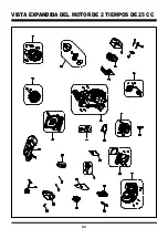
Page 82: ...82 VISTA EXPANDIDA DEL MOTOR DE 2 TIEMPOS DE 25 CC...

Page 83: ...1 6 321007188 Cubierta frontal del motor 1 7 321007189 Embrague 1 8 321007190 Cubierta de conexi n 1 9 321007191 Conjunto del volante 1 10 321007149 Conjunto de piezas del c rter 1 11 321007192 Pist...

Page 84: ...84 NOTAS...

Page 85: ...85 NOTAS...

Reviews: