background image

68

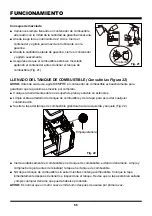
ARRANQUE Y PARADA DE LA BORDEADORA 

(Consulte las Figuras 25-31)

Para un arranque en frío:

■  Asegúrese de que la batería esté colocada firmemente.
■  Coloque la bordeadora sobre una superficie nivelada en exteriores.
■  Presione el pulsador de cebado 5 veces o hasta que se llene con combustible.
■  Gire la palanca de ahogue a la posición CHOKE (ahogar) (Fig. 25).

Fig. 25

FUNCIONAMIENTO

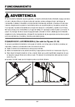
■  Levante la cubierta del botón de encendido, presiónelo y manténgalo presionado hasta que el motor 

encienda.  Gire manualmente la palanca de ahogue a la posición de RUN (accionar). Para obtener 
mejores resultados, permita que el motor se caliente sin usar la bordeadora durante al menos 1 
minuto, o apriete suavemente el acelerador para acelerar el proceso. Si aprieta el acelerador antes 
de que la bordeadora esté caliente, podría hacer que el motor se cale (Fig. 26 - 28).

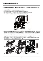
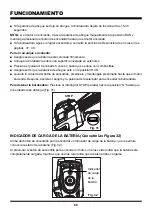
■  Para comenzar a cortar el pasto, active el seguro y la palanca del acelerador. No acelere el motor 

mientras presiona el botón de arranque (Fig. 29 - 30).

START

Fig. 26

Fig. 27

Fig. 28

Fig. 29

Fig. 30

Summary of Contents for NPTGSP2517A

Page 1: ...instrucciones de seguridad antes de utilizar esta herramienta 601 Regent Park Court Greenville SC 29607 SC 29650 1 866 384 8432 NOTICE Only use unleaded gasoline containing up to 10 ethanol Do not us...

Page 2: ...2 3 6 7 8 9 10 11 16 17 18 19 27 28 35 36 37 38 39 40 41 42 43 44 45 Engine Type Engine Displacement Claimed Rated Power Speed Idle Speed Max Torque Speed Fuel Tank Capacity Fuel Oil Ratio Line Diamet...

Page 3: ...zone there is still a risk of injury from thrown objects Bystanders should be encouraged to wear eye protection If you are approached stop the engine and cutting attachment Always wear eye protection...

Page 4: ...stopping the engine and letting it cool completely Do not smoke while fueling or mixing fuel Wipe spilled fuel from the trimmer Move at least 10 ft 3 m away from the fueling source and the site before...

Page 5: ...ure above 265 F 130 C may cause an explosion Do not modify or attempt to repair the battery pack as applicable except as indicated in the instructions for use and care Follow all charging instructions...

Page 6: ...rference to radio communications However there is no guarantee that interference will not occur in a particular installation If this equipment does cause harmful interference to radio or television re...

Page 7: ...ring protection when operating this equipment Precaution that involves your safety Gloves Wear non slip heavy duty protective gloves when handling this product Safety Footwear Wear non slip safety foo...

Page 8: ...garding available recycling and or disposal options SYMBOL SIGNAL MEANING DANGER Indicates an imminently hazardous situation which if not avoided will result in death or serious injury WARNING Indicat...

Page 9: ...9 KNOW YOUR GRASS TRIMMER 22 23 25 18 20 24 21 1 3 2 4 5 6 8 9 10 11 14 16 17 15 7 12 13 27 26 19...

Page 10: ...tor 18 Trimmer Line Cutting Blade 19 Debris Guard 20 Knob 21 Muffler 22 Engine Housing 23 Spark Pulg Cap 24 Throttle Safety 25 Start Button Cover 26 Shaft Connection Sleeve 27 Locking Pin 28 Charging...

Page 11: ...roduct requires assembly Carefully remove the product and any accessories from the box Make sure that all items listed in the packing list are included Inspect the product carefully to make sure no br...

Page 12: ...ckwise Align the axles in the shafts Pull out the locking pin and then insert the shaft into the shaft connection sleeve Fig 3 4 WARNING The trimmer line cutting blade on the debris guard is sharp and...

Page 13: ...Slightly rotate the shaft from side to side until the locking pin is locked into place Secure the shaft by turning the knob clockwise Fig 7 ASSEMBLY WARNING Ensure that the knob is fully tightened be...

Page 14: ...re the battery is inserted in the correct direction Fig 12 Do not use force when inserting the battery pack It should slide into position and click To remove the battery pack Press and hold the batter...

Page 15: ...rom the shoulder strap clasp Place the shoulder strap clasp against the drive shaft with the tapped hole on the left viewed from the engine Squeeze the two ends of the clasp together and hold in that...

Page 16: ...heck to ensure the shoulder strap is attached securely Fig 17 In case of emergency pull the rope of the quick release mechanism The release latch will be released from the tab and the machine will dro...

Page 17: ...fect the battery CHARGER LEDS If the battery is not connected to the charger a continuous green LED light indicates that the plug is plugged into an outlet socket and the battery charger is ready for...

Page 18: ...ecifications and then disconnect the charger from the power supply Remove the charging connector from the charging port Fig 20 NOTE It is normal for the battery pack and the charger to become warm but...

Page 19: ...s personal injury Before each use inspect the entire product for damaged missing or loose parts such as screws nuts bolts caps etc Tighten securely all fasteners and caps and do not operate this produ...

Page 20: ...out the United States contains ethanol The maximum ethanol content allowed by law for use in outdoor power equipment is limited to 10 E10 Most small power equipment engines are designed to use no more...

Page 21: ...and inspecting the tank Check that the cap is sealed tightly and wipe clean any spillage that may have occurred NOTICE It is normal for smoke to be emitted from a new engine after first use WARNING T...

Page 22: ...strap clasp and shoulder strap sold separately are used for your convenience balance the grass trimmer before starting the trimmer Loosen the screw on the shoulder strap clasp Slide the clasp to a com...

Page 23: ...in 15 30 seconds NOTE If the engine does not start manually turn the choke lever to the RUN position and hold the start button down until the engine starts If the trimmer continues to fail to start r...

Page 24: ...32 WARNING WARNING Always position the trimmer on your right side in order to reduce exposure to hot surfaces which can cause possible serious injuries Keep the bottom of the engine below waist level...

Page 25: ...he product Stop the engine if the grass becomes wrapped around the trimmer head and remove the grass once the cutting attachment has stopped rotating Extended use of the tool at partial throttle will...

Page 26: ...A firm but gentle motion should be used when tapping the line on the ground Fig 35 DO NOT keep the trimmer head pressed against the ground NOTICE The cutting blade on the underside of the debris guar...

Page 27: ...rside of the debris guard Fig 36 The cutting blade trims the line at a length that yields optimum cutting results If the engine is running faster than normal or it appears as though the trimmer is les...

Page 28: ...ety devices air vents and the motor housing free of dirt and dust Regularly clean the ventilation slot in your grass trimmer using a soft brush or dry cloth Regularly clean the cutting line and spool...

Page 29: ...y be cleaned with a cloth or soft non metallic brush CHARGER MAINTENANCE Keep the charger clean and clear of debris Do not allow foreign material into the recessed cavity or on the contacts Wipe with...

Page 30: ...You may wind new cutting lines onto an empty spool Replacement cutting line is available from a DIY store or online Remove the empty spool from the grass trimmer referring to the Spool Replacement se...

Page 31: ...T See Fig 44 Stop the engine and remove the battery pack Place the trimmer on a flat stable surface with the trimmer head facing upward Insert the provided hex wrench into the hole on the flange to lo...

Page 32: ...Spark arrestors may be in different locations depending on the model purchased Please contact your nearest service dealer for the location of the spark arrestor for your model IDLE SPEED ADJUSTMENT T...

Page 33: ...nk cap if required A clogged fuel filter will cause poor engine percformance Replace the fuel filter if required as it is a non serviceable part Please contact your nearest service center for replacin...

Page 34: ...gine Adjust spark plug gap by bending outer electrode Fig 50 Reinstall the cleaned or a new spark plug by turning it clockwise into place Fig 51 Reinstall the spark plug cap into place Fig 52 NOTICE B...

Page 35: ...cordingly Operating the engine with the wrong engine configuration at a given altitude may increase its emissions drop fuel efficiency reduce performance and cause irreparable damage Engines configure...

Page 36: ...nd corrosive materials are in the batteries used in this battery pack Lithium ion a toxic material To avoid injury and risk of fire explosion or electric shock and to avoid damage to the environment C...

Page 37: ...fuel tank Push the primer bulb until the bulb is full of fuel If the bulb does not fill the primary fuel delivery system is blocked Contact an authorized service dealer If the primer bulb fills the en...

Page 38: ...The line will not advance The line is welded to itself Lubricate the line with silicone spray Insufficient cutting line Install more line Refer to the Line Replacement section in this manual The line...

Page 39: ...that has become inoperative due to alteration misuse commercial use abuse neglect accident or improper storage or maintenance 2 The unit if it has not been operated and or maintained in accordance wit...

Page 40: ...40 EXPLODED VIEW NPTGSP2517A EXPLODED VIEW...

Page 41: ...321008101 Connection Cover Assembly 1 4 321008102 Aluminum Upper Shaft 1 5 141004102 Cable Clamp 2 6 321001109 Handle Spacer 2 7 321008103 Assistant handle 1 8 321008104 aluminium connector assembly 1...

Page 42: ...42 EXPLODED VIEW 25CC 2 CYCLE ENGINE...

Page 43: ...lation Sheet 1 6 321007188 Front Cover Assembly 1 7 321007189 Clutch Assembly 1 8 321007190 Connection Cover Assembly 1 9 321007191 Flywheel Assembly 1 10 321007149 Crankcase Assembly 1 11 321007192 P...

Page 44: ...44 NOTES...

Page 45: ...45 NOTES...

Page 46: ...62 63 64 73 74 82 83 84 85 86 87 88 89 90 91 92 Tipo de motor Desplazamiento del motor reportado nominal Potencia velocidad Velocidad en ralent Torque velocidad m xima Capacidad del tanque de combusti...

Page 47: ...todos los ni os personas cercanas y mascotas a una distancia de 50 pies 15 m fuera de la zona de 50 pies 15 m sigue habiendo riesgo de lesiones por los objetos que puedan salir expelidos Se debe insi...

Page 48: ...das con embrague aseg rese de que el accesorio de corte se detenga cuando el motor entre en ralent Cuando la unidad est apagada aseg rese de que el accesorio de corte se haya detenido antes de dejar l...

Page 49: ...en contacto con su piel l vese inmediatamente con agua y jab n luego neutralice con jugo de lim n o vinagre Si el l quido entra en sus ojos enju guelos con agua limpia por al menos 10 minutos y luego...

Page 50: ...t sujeto a las dos siguientes condiciones Este dispositivo no puede provocar interferencia da ina y Este dispositivo debe aceptar cualquier interferencia recibida incluida la interferencia que pueda p...

Page 51: ...nes El escape del motor de este producto puede exponerlo a qu micos que incluyen mon xido de carbono el cual basado en la informaci n que declara el Estado de California puede producir c ncer defectos...

Page 52: ...do opera este equipo Precauci n que involucra su seguridad Guantes Al utilizar este producto utilice guantes de protecci n antideslizantes y de alta resistencia Calzado de seguridad Al utilizar este p...

Page 53: ...cuanto a las opciones leg timas para desechar o reciclarlas S MBOLO SE AL SIGNIFICADO PELIGRO Indica una situaci n peligrosa inminente la cual de no evitarse podr a causar la muerte o lesiones severas...

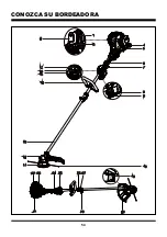
Page 54: ...54 CONOZCA SU BORDEADORA 22 23 25 18 20 24 21 1 3 2 4 5 6 8 9 10 11 14 16 17 15 7 12 13 27 26 19...

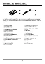
Page 55: ...dicador de carga de la bater a 18 Protector contra sedimentos 19 Hoja de recorte del hilo podador 20 Perilla 21 Silenciador 22 Carcasa del motor 23 Tap n de la buj a 24 Seguro del acelerador 25 Cubier...

Page 56: ...rios de la caja Aseg rese de que todos los elementos mencionados en la lista de componentes del empaque est n incluidos Inspeccione el producto cuidadosamente para asegurarse de que no se haya roto o...

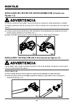
Page 57: ...je la perilla de bloqueo de la manga de conexi n del eje gir ndola en sentido antihorario Alinee los centros de los ejes Extraiga el pasador de bloqueo y luego inserte el eje en la manga de conexi n d...

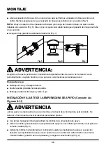
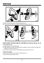
Page 58: ...letamente apretada antes de usar la herramienta revise peri dicamente el apriete durante el uso para as evitar lesiones personales graves INSTALACI N Y AJUSTE DE LA EMPU ADURA DE APOYO Consulte las Fi...

Page 59: ...a est insertada en el sentido correcto Fig 12 No utilice fuerza al insertar la bater a Debe deslizarse hasta su posici n y hacer clic Extracci n de la bater a Mantenga presionado el bot n de liberaci...

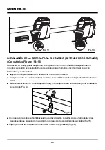
Page 60: ...talado de la hebilla de la correa para el hombro Coloque la hebilla de la correa contra el eje motriz con el orificio roscado a la izquierda mirando desde el motor Junte ambos extremos de la hebilla a...

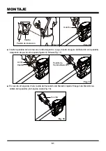
Page 61: ...de que la correa quede fijada con firmeza Fig 17 En caso de emergencia tire la cuerda del mecanismo de liberaci n r pida El seguro de liberaci n se soltar de la pesta a y la m quina caer Fig 18 Hebill...

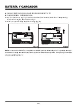
Page 62: ...rga no afecta a la bater a LED DE CARGA Si la bater a no est conectada al cargador una luz LED verde continua indica que el enchufe est conectado en una toma de corriente y que el cargador est listo p...

Page 63: ...sulte las especificaciones del producto y desconecte el cargador de la toma de energ a Retire el conector de carga del puerto de carga Fig 20 NOTA es normal que la bater a y el cargador se calienten p...

Page 64: ...No utilice este producto hasta haber instalado todas las piezas faltantes o da adas PELIGRO El combustible es MUY inflamable Tenga extremo cuidado al mezclar almacenar o manipular combustible de lo co...

Page 65: ...para exteriores tales como su equipo motorizado LawnMaster y hacer esto puede anular su Garant a Limitada de LawnMaster No obstante si toma las debidas precauciones la gasolina que contiene 10 de eta...

Page 66: ...para garantizar que la gasolina se mezcle por completo Coloque la herramienta sobre una superficie plana y estable en exteriores Limpie el rea alrededor del tanque de combustible y de la tapa para as...

Page 67: ...aneado encender el motor Mantenga la herramienta alejada de humo llamas abiertas y chispas El incumplimiento de las siguientes instrucciones podr a provocar explosiones incendios y lesiones personales...

Page 68: ...ido presi nelo y mant ngalo presionado hasta que el motor encienda Gire manualmente la palanca de ahogue a la posici n de RUN accionar Para obtener mejores resultados permita que el motor se caliente...

Page 69: ...le Aseg rese de que la palanca de ahogue est en la posici n RUN Levante la cubierta del bot n de encendido presi nelo y mant ngalo presionado hasta que el motor encienda Despu s acelere el seguro y la...

Page 70: ...o No toque esta parte de la herramienta durante el uso ni mientras siga caliente Al sostener la bordeadora aseg rese de que su cuerpo est alejado de la carcasa del motor El contacto con esta pieza pue...

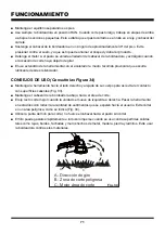
Page 71: ...de el silenciador CONSEJOS DE USO Consulte las Figura 34 Mantenga la herramienta hacia el lado derecho y alejada de su cuerpo para as evitar el contacto con superficies calientes Fig 33 Mantenga el ca...

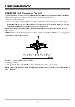
Page 72: ...tocar el hilo contra el suelo Fig 35 NO mantenga el cabezal de la bordeadora presionado contra el piso AVISO La hoja de recorte de la parte inferior de la protecci n contra sedimentos cortar el hilo...

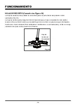
Page 73: ...ector contra sedimentos Fig 36 La hoja de recorte ajusta el largo del hilo de manera tal que se logre el resultado de corte ptimo Avance el hilo si el motor funciona a velocidad mayor de lo normal o s...

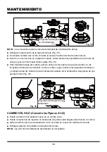
Page 74: ...ibles a da os causados por varios tipos de solventes comerciales Utilice pa os limpios y secos para retirar la suciedad polvo aceite grasa etc Mantenga todos los dispositivos de seguridad ventilacione...

Page 75: ...re de sedimentos No deje que materiales extra os entren en la cavidad o en los contactos Limpie con un pa o seco No use solventes agua o exponga el dispositivo a condiciones h medas Siempre desenchufe...

Page 76: ...ranuras de la tapa del carrete con las leng etas de bloqueo del cabezal como se indica Luego presione las leng etas de bloqueo y empuje la tapa del carrete hacia la carcasa del cabezal de la bordeador...

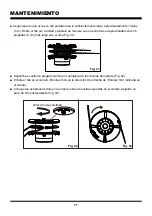
Page 77: ...a en el carrete Coloque los extremos del hilo en las dos ranuras de anclaje opuestas en el carrete dejando un poco de hilo sobresaliente Fig 43 Direcci n de enrollado Fig 42 Fig 43 Aseg rese de que el...

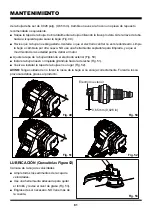
Page 78: ...ve hexagonal para bloquear el eje A continuaci n gire el cabezal de la bordeadora en sentido antihorario para instalarlo Aseg rese de que el cabezal de la bordeadora est instalado firmemente Quite la...

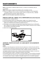
Page 79: ...motor Fig 47 Para restaurar el rendimiento lleve la bordeadora a un centro de servicio autorizado o persona calificada para que elimine el bloqueo El protector contra chispas debe limpiarse o cambiar...

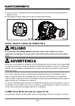
Page 80: ...uras 49 52 La buj a de este motor se puede cambiar usando una equivalente o id ntica a la original La brecha TAP N TANQUE Y L NEAS DE COMBUSTIBLE PELIGRO ADVERTENCIA El combustible es EXTREMADAMENTE i...

Page 81: ...a suciedad podr a da ar al motor Ajuste la tapa de la buj a doblando el electrodo exterior Fig 50 Instale la buj a nueva o limpiada gir ndola hacia la derecha Fig 51 Vuelva a instalar la tapa de la bu...

Page 82: ...reducir la eficiencia del combustible disminuir el rendimiento y causar da os irreparables Los motores configurados para grandes altitudes deber n reconfigurarse en caso de usarlos en condiciones de...

Page 83: ...ientes materiales t xicos y corrosivos est n en las bater as del paquete Litio ionizado un material t xico Para evitar el riesgo de incendio explosi n descarga el ctrica y da os al medioambiente Cubra...

Page 84: ...haya suficiente combustible en el tanque de combustible Presione el pulsador de cebado hasta que est lleno de combustible Si el pulsador no se llena el sistema de suministro de combustible est bloquea...

Page 85: ...n ralent debe ajustarse Contacte a un centro de servicio autorizado El hilo no avanza El hilo est pegado entre s Lubrique el hilo con un atomizador de silicona l quida No hay hilo de corte suficiente...

Page 86: ...operativa por culpa de una alteraci n mal uso uso comercial abuso negligencia accidentes y almacenamiento o mantenimiento inadecuados 2 La unidad en caso de que no se haya utilizado y o recibido mante...

Page 87: ...87 VISTA EXPANDIDA NPTGSP2517A VISTA EXPANDIDA...

Page 88: ...zas de la placa PCB 1 3 321008101 Cubierta de conexi n 1 4 321008102 Eje superior de aluminio 1 5 141004102 Pinza del cable 2 6 321001109 Espaciador de la manilla 2 7 321008103 Empu adura de apoyo 1 8...

Page 89: ...89 VISTA EXPANDIDA DEL MOTOR DE 2 TIEMPOS DE 25 CC...

Page 90: ...1 6 321007188 Cubierta frontal del motor 1 7 321007189 Embrague 1 8 321007190 Cubierta de conexi n 1 9 321007191 Conjunto del volante 1 10 321007149 Conjunto de piezas del c rter 1 11 321007192 Pist...

Page 91: ...91 NOTAS...

Page 92: ...92 NOTAS...

Reviews: