background image

crystal standard configuration User Manual

Version: 6.4.0/4

103/149

8. Operation

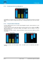
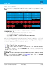
Count-Down Timer Operation

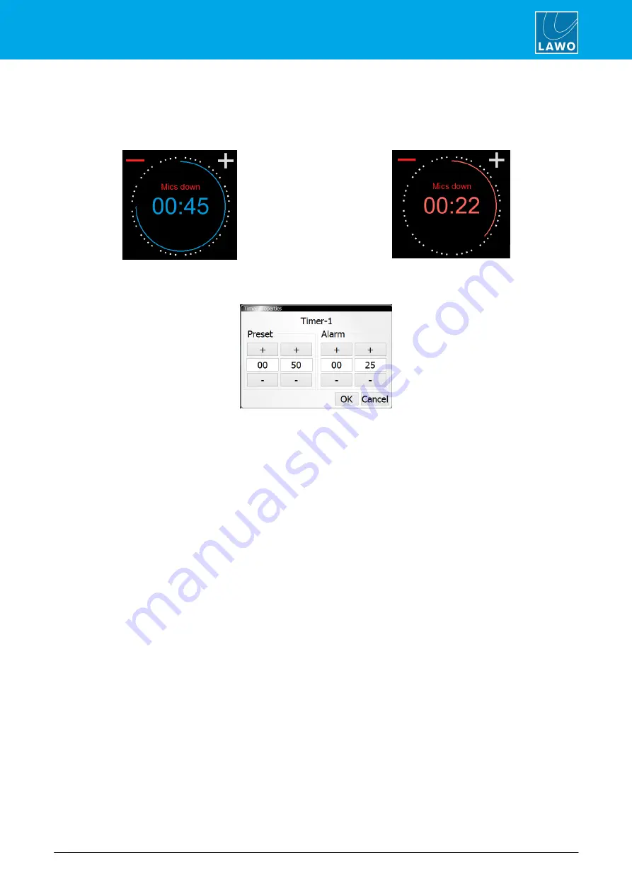
In this mode, the timer will count-down from a starting value (called the 

Preset

 time), and turn red once  a  mid-

point (the 

Alarm

 time) is reached:

Count-Down (before Alarm)

Count-Down (Alarm active)

1

.

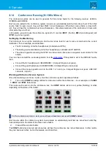
To  set  the 

Preset

  and 

Alarm

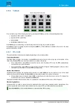
  time  values,  select  the  current  count-down  time  -  the  Timer  properties

window opens:

The 

Preset

 value defines the starting time. When you reset the timer, it will return to this setting - in our example,

to 50 seconds.

The 

Alarm

 value is used for the signalisation. When the count-down reaches this time, it turns red - for example,

at 25 seconds.

In both cases, use the minute and second fields to type in a value, or select the 

+

 and 

-

 buttons to increase and

decrease the current values. Then select 

OK

 to confirm.

2

.

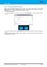
For our example, open one of the MIC source faders to start the count-down from the 

Preset

 time. 

When the count-down reaches the 

Alarm

 time, the numbers turn red to warn you that you are almost out of time.

If the count-down reaches 00:00, then the timer starts to count back up. This shows you by how much you are
overunning! In this instance, the Alarm status remains active until the timer is reset.

3

.

For our example, the timer stops once all MIC source faders are closed.

Note that the current time remains on-screen until the timer is reset.

4

.

To reset the timer, press the 

RESET

 key (on the Central Module).

Summary of Contents for Crystal standard configuration

Page 1: ...To obtain the latest documentation and software downloads please visit Edition Tuesday March 9 2021 Version 6 4 0 4 User Manual crystal standard configuration www lawo com lawo downloads...

Page 2: ...ers It cannot be guaranteed that all product names products trademarks requisitions regulations guidelines specifications and norms are free from trade mark rights of third parties All entries in this...

Page 3: ...er Manual Version 6 4 0 4 Table of Contents 1 Introduction 4 2 Important Safety Instructions 5 3 Product Overview 6 4 The Hardware 7 5 Specification 13 6 Installation 21 7 System Setup 31 8 Operation...

Page 4: ...for the following which indicate Notes points of clarification Tips useful tips and short cuts Attention alert you when an action should always be observed Further Information Mechanical drawings and...

Page 5: ...5 149 2 Important Safety Instructions 2 Important Safety Instructions Please observe all of the instructions provided in the General Safety Information for Lawo Equipment booklet delivered with your...

Page 6: ...active sources are the ones assigned to the fader strips and so the maximum number of mix inputs is determined by the console frame size Any available source can be assigned to any fader strip allowi...

Page 7: ...d configuration User Manual Version 6 4 0 4 7 149 4 The Hardware 4 The Hardware This chapter describes the hardware components and options Topics include Console Editions Control Surface Variants The...

Page 8: ...See AutoMix Channel On Off Operation On Fader Start consoles the channel on state is conditional on the fader position On Button Start consoles the channel on state is independent of the fader positio...

Page 9: ...ule to increase the fader count or create a split frame surface In total the control surface can include any number of extenders as long as the maximum number of faders does not exceed 24 Each frame c...

Page 10: ...te that the 4 fader main frame supports a single Central Module while all other sizes include two 4 fader 8 fader 12 fader 12 fader split 16 fader 4 fader extender 4 2 2 Placement Options crystal is d...

Page 11: ...redundant port The redundant connection is optional 4 ETHERNET The ETHERNET port connects other devices to the Compact Engine control system In a crystal standard configuration system it must connect...

Page 12: ...gnaling and switched functions 11 WCLK IN OUT WCLK IN can be used to connect an external sync reference The sync reference options are MADI WCLK IN AES3 or Internal WCLK OUT always provides an output...

Page 13: ...onfiguration User Manual Version 6 4 0 4 13 149 5 Specification 5 Specification This chapter describes the system specification Topics include Available Sources Available Buses Default Audio Assignmen...

Page 14: ...dec 3 4 RAV 01 03 stereo RAV In 1 3 RAV 04 28 stereo RAV In 4 28 MADI 01 MADI 32 stereo MADI ports 3 4 MADI channels 1 2 MADI channels 63 64 Fader Start FS Source Name Format Physical Input DSP Resour...

Page 15: ...on Button Start consoles Summing Bus Name Format Pickup Point Outputs PGM 1 stereo post fader see Default Audio PGM 2 stereo PGM 3 stereo AUX 1 stereo pre or post fader AUX 2 stereo PFL CUE stereo pre...

Page 16: ...fader strip assignments on the surface For the outputs the configuration loads the default audio assignments These can be modified from the local matrix in DisplayDock 5 3 1 Analog Inputs MIC LINE INP...

Page 17: ...NE 3 left right MON STUDIO 7 8 LINE 4 left right MON CR HEADPHONE SOCKETS Compact Engine rear panel Output Number Local Matrix Name Format Default Audio from HEADPHONE 1 HP 1 left right MON DJ HEADPHO...

Page 18: ...e Format 1 2 AES 4 left right 3 4 AES 5 left right 5 6 AES 6 left right 7 HYB 1 mono 8 HYB 2 mono 5 3 4 Digital Outputs AES3 OUTPUT Compact Engine rear panel Output Number Local Matrix Name Format Def...

Page 19: ...GM 1 3 4 RAV PGM 2 left right PGM 2 5 6 RAV PGM 3 left right PGM 3 7 8 RAV PGM 4 left right AUX 1 9 10 RAV AUX 1 left right AUX 2 11 RAV CODEC 1 mono RAV CODEC N 1 12 RAV CODEC TB mono RAV CODEC TB 13...

Page 20: ...mute 2 MIC 3 ON OFF COUGH ON OFF toggle if ON and push and hold 400 ms mute 3 MIC 4 ON OFF COUGH ON OFF toggle if ON and push and hold 400 ms mute 4 MIC 2 TALK INPUT MUTE MIC DJ HP and CR 5 MIC 3 TAL...

Page 21: ...ersion 6 4 0 4 21 149 6 Installation 6 Installation This chapter describes how to install the control surface and Compact Engine Topics include Installing the Control Surface Installing the Compact En...

Page 22: ...se check the contents of the shipping boxes and in the event of any transport damage contact your local Lawo representative or email support lawo com A list of serial numbers for all components is inc...

Page 23: ...m IEC power cable country specific to connect AC mains to the frame 1 x serial cable 485 0700 000 to connect to the RS 422 port for diagnostics Dust caps for the MADI connectors these will be mounted...

Page 24: ...ounting use standard third party 1RU recessed rack adapters such as the ones shown below When fitting the rack adapters and slide bars you must make sure that there is sufficient airflow through the d...

Page 25: ...eing grounded through Ethernet or other signal connections Grounding of Audio Interfaces For compliance with AES3 digital interfaces should be connected to a field ground For microphones the ground fr...

Page 26: ...n please see the Compact Engine Power Supply appendix If both inputs are connected then the two feeds provide main and redundant power To connect AC power to the frame 1 Using the IEC cable provided c...

Page 27: ...devices the latency of the communication will increase The control network MUST meet or exceed the following requirements At least 100MBit s 1 GBit s preferred Full Duplex It is important to keep the...

Page 28: ...is fitted with a RAVENNA IO Card 952 38 to stream audio to and from an IP network By default 32 stereo streams are transmitted and received via the ETHERNET A port while ETHERNET B remains unused The...

Page 29: ...ed Each of the 4 MIC LINE INs features a discrete class A preamplifier with superb performance at both low mic and high line levels In addition to variable microphone pre amp gain each input comes wit...

Page 30: ...to 48kHz but this can be changed to 44 1kHz from the DisplayDock GUI as described below Checking the Sync Reference The available and active sync sources can be checked from the DisplayDock Advanced...

Page 31: ...cribes how to install the software and set up the system Topics include System Connections Required for Setup Powering On Checking the System Setting Up the Control PC Configuring the System Licensing...

Page 32: ...to point a switch or hub is not allowed If more than one frame is supplied then the CAN bus must be daisy chained On the last surface in the chain fit the CAN bus terminator supplied with the system t...

Page 33: ...rt to the extender module CAN IN 2 Then connect the extender module CAN OUT to the CAN IN on the main surface 3 Fit the CAN bus terminator supplied with the system to the CAN OUT on the main surface 4...

Page 34: ...splay shows the device s IP address and the system run LED to the right of the RS422 connector begins to flash at regular intervals If the system run LED does not start to blink then the Compact Engin...

Page 35: ...t of the Compact Engine s ETHERNET port The Subnet Masks should be identical You can check the current network settings from the Compact Engine s front panel display The defaults are IP Address 192 16...

Page 36: ...vided At the Select Components window please accept all default options to install or update the components Note that the CodeMeter Runtime software is necessary for licensing If it is already install...

Page 37: ...hen all of the components have been installed the following window will appear Select Finish to exit the setup wizard and launch the DisplayDock Admin tool If you have any problems with the software i...

Page 38: ...s can then be transferred 7 4 1 Opening a Connection to the Compact Engine 1 DisplayDock Admin starts automatically at the end of the software installation procedure Alternatively select Program Files...

Page 39: ...Firmware Firmware Up to Date 7 4 2 Updating the Firmware If a new Firmware version is available then update the Compact Engine as follows 1 Click on Update to start the update procedure The Firmware s...

Page 40: ...ecting the correct console edition either Button Start or Fader Start the Config status updates accordingly 2 Click on Transfer Config to start the file transfer The Config status message shows update...

Page 41: ...has been entered correctly Then check the physical connections and the TCP IP settings of your computer s Network Interface Card 3 If new Firmware is available then this is shown in the status field...

Page 42: ...ow Multiple software products can be licensed from a single dongle USB Dongle for Lawo software 7 5 2 Preparing for Activation To activate a license you will need A PC with an internet connection and...

Page 43: ...er https licenseportal lawo com If necessary you can choose a different language using the drop down menu at the top right of the page 2 Copy your license ticket number this is the 25 digit number cod...

Page 44: ...en you will see an option to Get CmContainer automatically 6 Click on Activate Selected Licenses Now and wait for a few seconds a confirmation pop up appears once the activation is successful 7 After...

Page 45: ...enter the new IP address for the system and press ENTER 4 You are asked to confirm so type Y to confirm press ENTER The syntax is case sensitive so be sure to enter a capital Y You will see the follow...

Page 46: ...Start the application by selecting START Program Files SoP Explorer 2 Select Unit New from the main menus enter the IP address of the Compact Engine and select OK to add the unit SoP Explorer connect...

Page 47: ...r US East Coast where CET is 5 hours ahead The second part of the syntax specifies the start and end of Central European Summer Time CEST e g from month 3 week 2 day 0 time 2am the second Sunday in Ma...

Page 48: ...be configured and so on Please DO NOT attempt to connect the streaming ports using an unqualifying IP network as correct operation cannot be guaranteed You can find more details about the data network...

Page 49: ...orer as follows 1 Select the RAVENNA IO Card and then click on the run web browser icon the Comi MX Landing Page appears SoP Explorer opening the Landing Page Alternatively open a web browser applicat...

Page 50: ...A AES67 Streaming and then on the graphical preview to open the RAVENNA Web UI Home page Landing Page opening the RAVENNA Web UI RAVENNA Web UI Home page Note that the Landing Page preview uses a stat...

Page 51: ...ravenna and click OK The Home page updates to show all of the locked functions and Enable Edit Mode updates to Expert Settings to access to the Expert Settings menu 7 9 6 Default IP Settings The Comp...

Page 52: ...ess This allows it to be used for service tasks such as updating the IO card s firmware using SoP Explorer To edit the IP Settings 1 From the Network area click on an interface e g ra0 to view its ind...

Page 53: ...aster Slave mode and Slave Only mode For most installations Lawo recommends Slave Only mode In this mode the RAVENNA IO Card works in conjunction with an external PTP grandmaster clock This mode is re...

Page 54: ...is no source assigned to any of the Rx streams RAVENNA Web UI Default Stream Setup 1 Click on a Rx stream e g RAV In 1 and use the Stream Source field to select an incoming stream RAVENNA Web UI Rx S...

Page 55: ...ams The stereo Tx streams can also be pre labeled and connected from outputs by the configuration They can be seen in the Tx Streams list when you open the RAVENNA Web UI Home page Unless you wish to...

Page 56: ...er the MAC address to reveal its IP address Beside each streaming interface you will see passive if the interface is inactive or Slave if the interface is active and operating in Slave only mode You w...

Page 57: ...streams and connects them to the RAVENNA sources on the console In order to receive audio you must assign an incoming stream from the network as described earlier Once a Stream Source has been assigne...

Page 58: ...stream Green correct operation Red there is either no connection or no data Orange the stream is being received but there are drop outs in the data You will also see an icon on the right of each Rx s...

Page 59: ...ized every few seconds on the right is the peak value reached since the last reset Note that the Min Offset should never reach zero as this would mean that the buffer was empty Typically the Min Offse...

Page 60: ...ow to operate the system Topics include Basic Operations Fader Strip Control Source Specific Functions The Central Modules Assigning Fader Strips Bus Assign Input Gain Pan DSP Parameters Metering Moni...

Page 61: ...ut meters on the GUI and the Central Modules If the Compact Engine performs either a warm start or cold start while DisplayDock is running then the message System has been restarted appears on top of...

Page 62: ...lections The main page known as the DOCK appears on the right of the screen so that it can sit alongside other applications It provides master functions such as the system clock timer mic open indicat...

Page 63: ...This will scroll through all of the available pages 8 1 4 Shutting Down the System There is no special shutdown procedure for the hardware components and so you can turn off the control surface and th...

Page 64: ...arameter control or activate strip assign mode The operation is as follows Press a fully lit ACCESS key once to select a source the key turns white On DisplayDock the Source Parameters page shows the...

Page 65: ...add or remove a channel from the PGM outputs The channel on off operation differs in the following ways Fader Start Consoles The fader motors are active and the channel on state is conditional on the...

Page 66: ...e the conference The conference system is described in more detail later TEL this key lights when a telephone call is incoming Press the key to capture the call on the console AMix enable this key to...

Page 67: ...output on the right The meters work in parallel with the meters on the DOCK 2 Ambient Light Detector This detector automatically adjusts the brightness of buttons and displays on the control surface...

Page 68: ...For more information see Using the Local Snapshot Memories and local matrix 5 Monitoring Controls The remaining keys and rotary controls provide monitor source selection and volume control for the fou...

Page 69: ...witches into strip assign mode and the Source Assignment buttons appear on DisplayDock Fader Strips source assign mode DisplayDock source assign view Scroll down for more sources On DisplayDock the bu...

Page 70: ...make the assignment the fader label updates and the strip assign mode cancels Alternatively select REMOVE to remove the source the fader strip is cleared and strip assign cancels The CANCEL button ca...

Page 71: ...s assign mode and their soft keys show the current assignments Yellow post fader Green off not assigned Red pre fader available for AUX buses only 2 Press a soft key to assign or de assign the source...

Page 72: ...ation User Manual Version 6 4 0 4 72 149 8 Operation 8 6 2 Assigning a Bus to an Output By default the summing buses are assigned to a number of physical outputs and Tx streams These are listed under...

Page 73: ...a stereo source this changes to left right balance 1 Turn the rotary control to adjust the first parameter you will see both its name e g Mic gain and value e g 42dB 2 Press down on the rotary control...

Page 74: ...ely you will need to ask the talent to speak into the microphone at their intended on air level 1 Start by asking the talent to speak and then turn on AutoGain by pressing the MIC source ACCESS key an...

Page 75: ...8 1 Signal Flow MIC Source Signal Flow The DSP available for each source is defined by the configuration and cannot be changed by the user Each of the MIC sources comes fully configured with analog a...

Page 76: ...eter control mode and on DisplayDock the Source Parameters page appears DisplayDock Source Parameters page Control Surface INPUT parameters DisplayDock shows all available parameters and so this is th...

Page 77: ...eled by the displays as shown above Then press a soft key e g Pad to turn the option on or off red on green off Turn a rotary control e g Mic to adjust its value the current value e g 42dB is shown in...

Page 78: ...DisplayDock For a mono MIC source you can adjust input parameters in the analog domain before the A D converter AND in the digital domain after the converter The analog mic preamp section includes MI...

Page 79: ...uts are summed with a 3dB gain offset SIDE the left input and right input are reversed left input to right side of channel and right input to left side of channel GAIN channel gain from 30dB to 18dB B...

Page 80: ...ACCESS key on any MIC source on DisplayDock the Source Parameters page appears From the REDLIGHT area 1 First choose a red light either CR or STUDIO the selection turns red 2 Then assign the MIC sourc...

Page 81: ...ccess the dyanmics parameters press an ACCESS key followed by DYN on the Central Module The fader strip controls update to show the last page adjusted in our example the Compressor Surface Controls Co...

Page 82: ...RLS release time from 10ms to 5000ms For the ATT RLS control turn to adjust the attack time and then press down and turn to adjust the release time Both DYN and COMP must be enabled red for the compre...

Page 83: ...DYN on off for all dynamics sections compressor expander gate and de esser automix EXP on off for the expander THRS threshold from 93dB to 27dB RATIO ratio from 1 1 to 1 0 1 Both DYN and EXP must be...

Page 84: ...x GATE on off for the gate THRS threshold from 93dB to 27dB ATT attack time from 0 16ms to 82ms RLS release time from 10ms to 5000ms For the ATT RLS control turn to adjust the attack time and then pre...

Page 85: ...s is the amount of gain reduction applied to the sibilant frequencies o Values from 1 to 6 reduce the gain of the unwanted sibilant frequenices the higher the value the more gain reduction o Above 6 t...

Page 86: ...ser automixing AMix on off for AutoMix Weight adjusts the weighting factor of each source from 9 to 9 with a default mid point 0 Sources with a higher weight value get priority in the mix those with t...

Page 87: ...iter parameters press an ACCESS key followed by LIM on the Central Module Surface Controls Limiter DisplayDock The following parameters are available for the Limiter LIM on off for the limiter red on...

Page 88: ...ic EQ plus high pass and low pass filters The filters can be used either as fixed slope filters 12dB per octave or shelving EQ To access the EQ parameters press an ACCESS key followed by EQ on the Cen...

Page 89: ...band the following parameters are available Gain Low Mid and High Gain can be adjusted from 15dB to 15dB Frequency Low Mid and High Frequency can be adjusted from 20Hz to 18kHz Q press the or buttons...

Page 90: ...ose a high frequency shelf High or Low Pass Filters In this mode the filter slope is fixed at 12dB per octave Therefore there is no Gain or Q value available The cut off frequency can be adjusted from...

Page 91: ...e meter automatically switches to the pre fader listen bus level It will return to the active monitor source once all PFL CUE selections are cleared PGM 1 always meters the PGM 1 output Both meters ar...

Page 92: ...red using either a Momentary 400ms sliding window or Short term 3s sliding window integration time The color indicates whether loudness is above or below the Target Level Light Blue equal to or below...

Page 93: ...omentary loudness metering as described earlier Output Metering On the top row are meters for the summing buses PGM 1 PGM 2 PGM 3 and AUX 1 Note that a dedicated meter for AUX 2 is not available but i...

Page 94: ...d MUTE and DIM buttons on the surface for the speaker outputs the split headphones option available for the MON DJ and the automatic dimming of the MON CR output by an active redlight If PFL or CUE bu...

Page 95: ...sources and other options are then available via the Monitor Extension pop ups on DisplayDock These can be opened by pressing any of the wide buttons below the volume controls e g press CRM to open t...

Page 96: ...ess additional monitor sources and other options DisplayDock supports a Monitor Extension for each of the monitor sections To open an extension press the wide button below the section s volume control...

Page 97: ...ghts in red MON CR Extension MON STUDIO Extension MON DJ Extension MON GUEST Extension Split Headphones There is one additional option for MON DJ output called SPLIT When SPLIT is active red the DJ wi...

Page 98: ...sed fader press PFL to route the source onto the stereo PFL bus the PFL automatically cancels when you open the fader On an open fader press PFL to put the channel into PFL Prepare Nothing happens unt...

Page 99: ...are either resolved or acknowledged on the Advanced page 8 11 2 System Clock Timer DisplayDock includes both a system clock and count up count down timer By default the clock appears big with the time...

Page 100: ...timer in count up mode Click on the sign it turns red to change the timer to count down mode The triggering method is selected from the Central Module using the AUTO key AUTO on automatic timer mode...

Page 101: ...n mode using the and signs on the GUI Count Up Timer Count Down Timer In count up mode the timer will count up from 00 00 In count down mode the timer will count down from a Preset value described lat...

Page 102: ...e TIMER AUTO MODE option indicates this red auto mode on blue auto mode off 3 Set your count up or count down mode using the and signs on the GUI In our example MIC ONLY is selected in step 2 and so y...

Page 103: ...is time it turns red for example at 25 seconds In both cases use the minute and second fields to type in a value or select the and buttons to increase and decrease the current values Then select OK to...

Page 104: ...l status ON OFF The MIC OPEN status can also trigger two external red lights one in the control room and one in the studio by preparing the REDLIGHT options in DisplayDock 8 11 6 CALL Signaling Displa...

Page 105: ...o delete a DisplayDock snapshot Snapshots are described in more detail later CLOCKING The CLOCKING area shows the active sync source and sample rate The SYNC fields are indicators only you cannot chan...

Page 106: ...perates in manual mode The color of the option indicates this red auto mode on blue auto mode off For more information see Timer Operation USER LABEL This option sets the size of the user labels displ...

Page 107: ...lready assigned then its button is red If no audio is assigned then the button is blue Note that the assignments shown above are the default audio assignments for a Button Start console The default au...

Page 108: ...esigner configuration and cannot be changed By default a source uses its Display name unless a System name is entered 3 Use the Line 1 and Line 2 fields to edit the two user label lines up to 8 charac...

Page 109: ...inus return there are no separate level controls for this output You can check and edit the audio assignments from the local matrix If the system is set to the DEFAULT audio then Connect the DJ headph...

Page 110: ...rsation Also if you close the DJ fader the DJ s monitor feed reverts to a conference bus mix minus so they can rejoin the off air conversation if required 4 Finally open both the MIC 1 and MIC 2 fader...

Page 111: ...s are stored and recalled by all snapshots Fader Strip Assignment the assignment of sources to fader strips User Labels the two User Label text lines for all sources DSP settings Input Parameters EQ D...

Page 112: ...NAP RECALL You can see which memories contain data by looking at the lit buttons in our example there is data stored in memories 1 2 4 and 5 2 Keep holding SNAP RECALL and select a memory e g number 4...

Page 113: ...only the settings for the source in access The SAVE SNAP button on the DOCK supports both operations as follows To save a Full snapshot 1 Check that there is no source in access and select SAVE SNAP...

Page 114: ...rns white and the Source Parameters page appears on DisplayDock Notice that the SAVE SNAP button has updated to SAVE SOURCE 2 Select SAVE SOURCE the Save Access window appears 2 Enter a snapshot name...

Page 115: ...ts can be loaded either to the source in access OR to their original source if nothing is in access The original source is identified in the Source column 2 Select a snapshot from the list and select...

Page 116: ...hots are stored on the control PC in a file named VisConfigurations mdb After a standard installation of the DisplayDock software the file can be found at C ProgramData DSA DisplayDock Crystal databas...

Page 117: ...ystal standard configuration User Manual Version 6 4 0 4 117 149 9 The Web UI 9 The Web UI This chapter describes the Web UI Topics include Introduction Opening a Session The System Page TCP Connectio...

Page 118: ...e Web UI 9 1 Introduction The Web UI provides status information about the system It is accessed by entering the IP Address of the Compact Engine you wish to examine into a Web browser The computer yo...

Page 119: ...pact Engine IP address on the front panel display The default IP Address 192 168 101 240 Following a successful connection the System Page appears The Web UI has two pages system and TCP connections U...

Page 120: ...ere is plenty of memory left and in red if the available memory falls below 20 Last Restart the date and time of the last system restart Config loaded the date and time when the last configuration was...

Page 121: ...d time Voltage the current voltages within the system Fan 1 and 2 the fan speeds within the Compact Engine Temperature Proc Unit Compact Engine the current internal temperatures of the Compact Engine...

Page 122: ...thin the configuration Card ID act the card ID actually fitted and running within the slot Card type act short description of the card type GPIO the status of the contacts on a GPIO card Status the va...

Page 123: ...ation User Manual Version 6 4 0 4 123 149 9 The Web UI 9 3 7 Client Connections The Client Connections show all network clients connected to the system For example the IP Addresses of any networked sa...

Page 124: ...P Connections This page displays the network connections to the Compact Engine and the state of those connections Netcom Connections systems connected via GNET GPIO Network DMS Connections systems con...

Page 125: ...l Version 6 4 0 4 125 149 10 Maintenance 10 Maintenance This chapter describes the maintenance procedures available for the system Topics include Restarting the System Compact Engine Procedures Contro...

Page 126: ...rm start by pressing the RESET button on the front panel The button is recessed to prevent accidental operation Front View A warm start will reboot the device Do NOT perform a warm start while live on...

Page 127: ...g data transfer LED 2 right System Run LED green flashing the control system has booted and is running normally 10 2 2 Service Mode Front View The Compact Engine can be booted in service mode to perfo...

Page 128: ...e Load Default Parms option is canceled 1 Boot the unit in service mode and page through to Load Default Parms 2 Press the OK button to toggle between the YES and NO options and select YES 3 Power off...

Page 129: ...Type 2 to view the last test results Note that the memtest command is only valid while the unit is running in Boot Mode 10 2 3 Replacing Defective Parts The IO cards fitted to expansion slots 1 and 2...

Page 130: ...ow does not appear then the Telnet Client option may be disabled in Windows This can be remedied by turning on Telnet Client in your Windows Control Panel If the Telnet Client option is activated and...

Page 131: ...eraterm 2 Connect your PC directly to the RS 422 port on the Compact Engine s front panel A suitable cable is delivered with every unit article number 485 0700 000 This provides a RJ45 connector for t...

Page 132: ...uble click on the links below to open the special functions mode documentation as a pdf crystal Fader Module SF mode crystal Monitor Module SF mode 10 3 2 Replacing Defective Parts The CAN bus is hot...

Page 133: ...ge caused by unauthorized use of disinfectants on radio products and console surfaces This is a general instruction and recommendation for cleaning that applies to all Lawo radio products Before you c...

Page 134: ...134 149 11 Appendices 11 Appendices This chapter includes further information which you may find useful Topics include Part Numbers System Reference Levels Connector Pin Outs crystal Surface Power Sup...

Page 135: ...951 41 10 Central Monitor Module 951 41 20 crystal Compact Engine Main Frame 952 30 RAVENNA IO Card front expansion slot 952 38 LINE IO Card front expansion slot 952 31 AES IO Card front expansion sl...

Page 136: ...0 dBr for the ARD German Broadcasters Network is at 9 dBFS From this follows a Relative System Level dBFS of 27 Note that the working point is important as dynamics and limiter modules refer to this...

Page 137: ...crystal standard configuration User Manual Version 6 4 0 4 137 149 11 Appendices 11 3 Connector Pin Outs...

Page 138: ...t Mechanical data Width 72 mm Height 35 mm Length 175 mm Weight 670 g Cable length without plug 1200 mm Electrical Specification Parameter Conditions Min Typ Max Unit Input Voltage 100 240 VAC Frequen...

Page 139: ...eter Conditions Unit Mechanical data Width 72 mm Height 35 mm Length 175 mm Weight 670 g Cable length without plug 1200 mm Electrical Specification Parameter Conditions Min Typ Max Unit Input Voltage...

Page 140: ...first two steps from the online activation method Open the Lawo License web browser page at https licenseportal lawo com Copy your license ticket number this is the 25 number code into the Ticket fiel...

Page 141: ...o License web portal copy the license update file back to the original computer Import the license update file to the Cm storage container Creating the License Request File On the computer you wish to...

Page 142: ...quest file Select Add license of a new producer Enter the Lawo FirmCode 102037 4 Select Next and using Windows Explorer enter a file path for the license request file Choose somewhere easy to find suc...

Page 143: ...thod Open the Lawo License web browser page at https licenseportal lawo com Copy your license ticket number this is the 25 number code into the Ticket field and select Next When your license is displa...

Page 144: ...indows Explorer choose the request file created earlier 4 Then select Upload Request And Continue Now the license request is processed and if successful you will have the option to Download the update...

Page 145: ...the one selected earlier during the License Request 2 Select License Update and follow the instructions given by the CmFAS Assistant when prompted select Import License update and choose the update fi...

Page 146: ...o products or software versions you will see several LAWO AG containers If a USB dongle is connected you will see a container labelled CmStick Local Computer Container LAWO AG USB Dongle Container CmS...

Page 147: ...e is handed back to the server where it may then be used by a different VisTool client Preparing the License Server 1 First install the Codemeter Runtime software Version 5 10 or above on the central...

Page 148: ...age select the name of the computer a dialogue box should appear listing all the available license servers 5 Choose the correct server from the drop down list and click on Select If the license server...

Page 149: ...w one of the server licenses as follows 1 On the client computer open the Codemeter Control Center and select WebAdmin 2 Under Content Licenses choose the CmContainer holding the server licenses and s...

Reviews: