crystal standard configuration User Manual
Version: 6.4.0/4
32/149
7. System Setup
7.1
System Connections (Required for Setup)
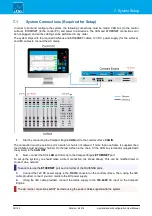
In order to boot and configure the system, the following connections must be made: CAN bus (to the control
surface), ETHERNET (to the control PC) and power to all devices. The CAN and ETHERNET connections can
be hot-plugged, and so the cabling can be performed in any order.
The system ships with the required CAN bus and ETHERNET cables, 12V DC power supply (for the surface)
and IEC cables to connect the AC mains.
1
.
Start by connecting the Compact Engine
CAN
port to the control surface
CAN IN
.
The connection
must
be point-to-point; a switch or hub is not allowed. If more than one frame is supplied, then
the CAN bus must be daisy-chained. On the last surface in the chain, fit the CAN bus terminator (supplied with
the system) to the
CAN OUT
.
2
.
Next, connect the PC's
LAN
port
directly
to the Compact Engine
ETHERNET
port.
To set up the system, you should make a direct connection (as shown above). This can be modified later to
connect via a network.
Take care to use the
ETHERNET
port and
not
either of the RAVENNA ports.
3
.
Connect the 12V DC power supply to the
DC IN
connector on the control surface. Then, using the IEC
cable provided, connect your AC mains to the DC power supply.
4
.
Using the IEC cable provided, connect the mains supply to the
100-240V
AC input on the Compact
Engine.
The AC mains connections
MUST
be made using the power cables supplied with the system.


