background image

Defender Press Brake Guarding System Operation Manual 

LS-CS-M-069 

Page 5 

Original Language Version: 1.04 


Released: 

01/04/2020


3


System Overview 

The Lazer Safe Defender Press Brake Guarding System is a guarding system designed for 
hydraulic press brakes that provides a highly effective solution for both operator protection 
and machine productivity. 

3.1


Key Benefits 


Defender gives the operator unrestricted access to the tooling area. 


The operator can hold the work piece as close as 20mm to the bend line and operate 
the machine at high speed. 


Complex shapes can be produced with the "Tray/Box" and "Field Muted" modes of 
operation.  


The  Defender  system  continuously  monitors  the  machine  speed  and  stopping 
distance in real time. 


A  flat  band  of  continuous  laser  light  detects  obstructions  as  small  as  4mm  while 
remaining vibration tolerant. 


The mute point is set on the first stroke. The laser guard detects the material position, 
and the operator confirms the mute point. 


Failure detection is performed by real-time monitoring of the process under control. 


The Defender system can be installed either at the time of manufacture or as a retrofit 
to a press brake already in service. 


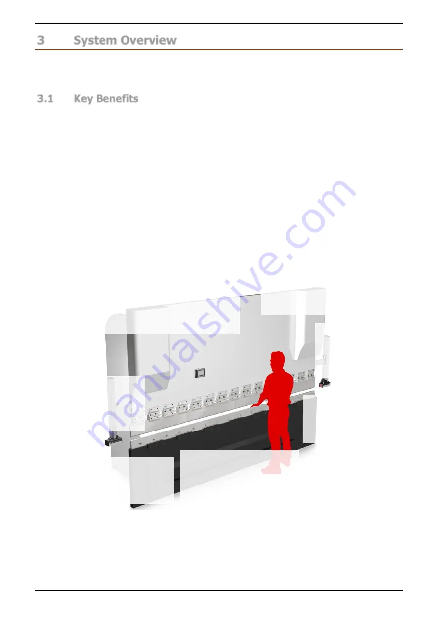
Figure 3-1: Defender Press Brake Guarding System Key Features 


Defender User Interface Panel  

The 4.3” colour graphics display 
makes the system very simple to 
operate.  A  magnetic  backing 
allows  the  panel  to  be  easily 
moved. 

Laser Transmitter (TX) 

A single planar laser is projected under the 
tooling  which  can  detect  obstructions  as 
small as 4mm, on machines up to 6m long. 
The  laser  protection  is  muted  as  the  tools 
close, 2mm above the material. 
 

Automatic Mute Point Set-up 

The mute point set-up is automatically initiated on the first cycle. The 
laser  detects  the  material  surface  and  the  operator  is  prompted  to 
confirm  the  mute  point  via  the  User  Interface  Panel.  The  system 
automatically monitors the mute position and detects changes in tool 
size and material thickness. 

Close Proximity Protection 

Defender gives the operator unrestricted 
access to the tooling area. The operator 
can hold the work piece as close as 
20mm from the bend line, and still 
operate the machine safely in high speed. 

Laser Receiver (RX) 

The RX features a wide reception 
zone  to  eliminate  the  need  for 
precise  manual  adjustment  after 
tool  change.  LEDs  simplify  the 
setup and adjustment. 

Advanced Monitoring Functions 

Defender 

automatically  monitors 

machine performance in real time. 
 

Quick Adjust Brackets 

The  TX  and  RX  can  be 
quickly  moved  clear  during 
tool  change,  are  easily 
adjusted  and  highly  tolerant 
to machine vibration. 

Summary of Contents for LS-CS-M-069

Page 1: ...DEFENDER PRESS BRAKE GUARDING SYSTEM Operation Manual LS CS M 069 27 Action Road Malaga WA 6090 Australia PO Box 2368 Malaga WA 6944 Australia 61 8 9249 4388 61 8 9249 6011 info lazersafe com...

Page 2: ...nder Press Brake Guarding System Operation Manual LS CS M 069 Page i Original Language Version 1 04 Released 01 04 2020 Document Status Document Reference Code LS CS M 069 Version 1 04 Released 01 04...

Page 3: ...tart up sequence Added External Stop at Mute Added mute reset message Added E Stop menu description Added Restricted mode crawl description General corrections 19 07 2017 1 02 Added periodic alignment...

Page 4: ...rks of Microsoft Corporation in the U S A and or other countries The content of this manual is supplied for informational use only is subject to change without notice and should not be construed as a...

Page 5: ...European Union 4 2 3 3 Requirements for Retrofitted Systems All Locations 4 2 3 4 Equipment Alterations 4 3 System Overview 5 3 1 Key Benefits 5 3 2 System Components 6 3 3 Optical Protection Overvie...

Page 6: ...1 5 6 Menu Screen 22 5 6 1 User Guides 23 5 7 Info Screen 23 5 7 1 System Information 24 5 7 2 Machine Information 24 6 System Operation 25 6 1 Power up 25 6 2 Start up Test 25 6 3 Setting the Mute Po...

Page 7: ...eter 4 Language 42 8 Operator Instruction and Demonstration 43 8 1 Equipment Identification 43 8 2 Starting the System 43 8 3 Mute Point Setting 43 8 4 Operation in Normal Mode 44 8 5 Tray Tray 2 Back...

Page 8: ...that complies with established safety practices 1 3 Document Organisation This manual is organised into the following chapters 1 About This Manual 2 Critical Safety Information 3 System Overview 4 Tr...

Page 9: ...bol indicates danger You are in a situation that could cause bodily injury Before you work on any equipment be aware of the hazards involved with electrical circuitry and be familiar with standard pra...

Page 10: ...re the highest possible degree of safety in operating a press brake fitted with the Defender Press Brake Guarding System it is important to note the following special warnings Warning AVOID FAST ERRAT...

Page 11: ...nt prevention 2 3 3 Requirements for Retrofitted Systems All Locations The combination of a press brake and the Defender system must comply with the relevant local regulations that apply to machine sa...

Page 12: ...1 Defender Press Brake Guarding System Key Features Defender User Interface Panel The 4 3 colour graphics display makes the system very simple to operate A magnetic backing allows the panel to be easi...

Page 13: ...the LZS 1 transmitter and receiver pair The transmitter and receiver are mounted on the upper beam of the press brake allowing the operator to remain close to the work piece as the tools close at hig...

Page 14: ...laser transmitter as this will void the product warranty and may expose you to the internal laser emitter CLASS 3R LASER RADIATION that has the potential to cause eye damage 3 3 3 Setup Prior to oper...

Page 15: ...Mute Point Distance 3 3 4 Mute Point The mute point is the point where the optical protection is turned off so that the material being formed cannot cause an obstruction During the setup procedure the...

Page 16: ...e Normal mode behaviour is slightly different from that described above due to the configuration of the up acting hydraulics An additional control input is provided the Open Tools Enable button When t...

Page 17: ...peed only with the optical protection muted and display the message LASERS INACTIVE until the bend is completed The sensors become active again once the tools are opened 3 5 3 Tray 2 Mode Tray 2 mode...

Page 18: ...sures that the machine does not exceed safe speed in this mode particular caution must still be exercised Entry to Field Muted mode can be password protected and should only be used by suitably traine...

Page 19: ...e Mute Mode Restricted 2 option enforces the following conditions Crawl speed is not permitted in Normal Tray or Field Muted modes Any obstruction prohibits tools closing Tool Setup mode is enabled 3...

Page 20: ...nguage Version 1 04 Released 01 04 2020 The system also monitors the machine process for failures of hydraulic valves failures of electrical components and failures in the machine controller software...

Page 21: ...pper tools the brackets can be quickly moved up and locked clear so that the punch can be removed from the ends of the press beam To release the vertical bracket unscrew the locking handle raise the t...

Page 22: ...Distance Align the laser to the high contrast receiver targets Permanently set your laser to punch distance with the adhesive guides Figure 4 3 Tool Locator Tabs To assist in setting the laser to punc...

Page 23: ...cket to release the clamp Slide the bracket up or down until the laser is positioned in the slots on the transmitter alignment card Then tighten locking handle to secure the bracket Remove the alignme...

Page 24: ...iodic Alignment Check The alignment of the transmitter receiver and punch should be checked using the supplied Lazer Safe alignment cards at the following times After system start up After each tool c...

Page 25: ...1 Parameter N Parameter 0 Parameter 1 Parameter N Parameter 0 Parameter 1 Parameter N User Guide 0 User guide 1 User Guide N Requires System access code Figure 5 2 Defender Menu Levels Note An operat...

Page 26: ...atus and Action screens of the Defender User Interface for further information If the error cannot be cleared contact your supplier or Lazer Safe Customer Support for assistance 5 3 Optional Indicator...

Page 27: ...mpted for action by Action window message The Action window prompts the operator with the action required to complete the current operation For example if a fault condition occurs the error message an...

Page 28: ...ew of the menu system GUARD MODE This button cycles through the guard modes Normal Tray Tray 2 Normal etc FIELD MUTED If this button is enabled it toggles the Field Muted mode The functionality of thi...

Page 29: ...re set during the installation of the Defender Press Brake Guarding System a SUPERVISOR MENU USER MENU SYSTEM MENU USER GUIDES Make a selection Figure 5 6 Menu Screen Label Button Function This leaves...

Page 30: ...e step by step graphical guides for common procedures that need to be performed regularly on Lazer Safe equipment such as how to align LZS 1 laser guards If the guide contains more than one page the l...

Page 31: ...sion PGS 2 Safety Controller FPGA firmware version Approx slow point The slow speed point calculated by the Defender The press brake must be travelling in slow speed by this opening in millimetres Las...

Page 32: ...d Idle screen as shown in Figure 6 1 Whenever the machine is idle for more than five minutes it will return to the Idle screen Figure 6 1 Defender Idle Screen 6 2 Start up Test When first started the...

Page 33: ...will start closing in high speed and then automatically stop after a short distance Depending upon the way the Sentinel has been configured the test will be performed after 20mm 50mm or 70mm of high...

Page 34: ...MENU MODE SELECT TOOL SETUP SET INFO ACTION PRESS FOOT PEDAL SET MUTE POINT 0000 A STATUS STD Figure 6 4 Set Mute Point Prompt Screen Figure 6 5 Material Placement on the Die Note During mute point s...

Page 35: ...RM MUTE POINT PRESS SET BUTTON as shown in Figure 6 7 If an external mute lamp has been installed the lamp will light MENU MODE SELECT TOOL SETUP SET INFO ACTION PRESS SET BUTTON CONFIRM MUTE POINT 00...

Page 36: ...5 Selecting Tray Box Modes To change the optical protection mode the Defender panel must be in the Mode Select screen From the Main screen press the MODE SELECT button and the screen will change to th...

Page 37: ...point is stored in system memory and does not need to be set again when changing to Tray Box mode If the operator needs to reset the mute point while in Tray Box mode the procedure is the same as desc...

Page 38: ...nsor window now indicates that there is no optical protection no sensor state is displayed If an external mute lamp has been installed this will also be turned ON FIELD MUTED FIELD MUTED FIELD MUTED F...

Page 39: ...reen will change to the Mode Select screen When changing modes the tools must be open with the laser above the mute point and clear of any obstructions If these conditions are not met the Status windo...

Page 40: ...bled and remain enabled Unlock the foot pedal OFF Stop at Mute mode will be disabled the next time the press moves up to TDC If the press is at TDC when the input is switched off one more stroke will...

Page 41: ...Open tools to enable button function Warning NO OPTICAL PROTECTION IN TOOL SET UP MODE In Tool Setup Mode all optical guarding is deactivated Although the Defender Press Brake Guarding System ensures...

Page 42: ...n E Stop of the machine Normal operation cannot be continued until the E Stop switch is reset Rear Gate A safety switch is connected to the rear gate of the press brake and triggers an E Stop when the...

Page 43: ...s the number of the monitor 1 2 3 or 4 B is the type of failure either on or off If the Defender detects any voltages on the EDM inputs and the system has not been configured for EDM it will display t...

Page 44: ...ess the Supervisor level menu This menu contains machine site specific parameters that are set during the installation of the Defender Press Brake Guarding System The System menu is not described in t...

Page 45: ...arrow buttons step through the parameter list the parameter is selected by pressing the ENTER button Note Lists and values that are navigated using arrow keys always appear as loops When the end of th...

Page 46: ...ged is underlined by a cursor starting with the left most digit i e the digit 1 in Figure 7 3 below The buttons are pressed to increment or decrement the value of the underlined digit Once the digit h...

Page 47: ...red option has been selected press the ENTER button the value will be written into the Defender s non volatile memory and the system will return to the parameter list 7 3 Supervisor Menu The Superviso...

Page 48: ...o navigate the options Changes can be abandoned at any time by pressing the button When the desired option has been selected press the ENTER button the value will be written into the Defender s non vo...

Page 49: ...button to navigate the digits and the buttons to change each digit value Changes can be abandoned at any time by pressing the button When the desired digit has been set press the ENTER button the valu...

Page 50: ...emonstrate and explain the start up test Demonstrate the stopping test during start up and explain how it tests the safety stopping performance of the machine and either passes or shuts the machine do...

Page 51: ...cluding the need for a confirmation pedal press at the beginning of each stroke Explain the reason for Back Gauge mode and the elevated rear sensor mute height 16mm 8 6 Field Muted Mode Refer to Secti...

Page 52: ...he Defender panel 8 10 Running the System Have the operator perform each of the main functions Using each mode of the system have the operator bend some test pieces of material and also making sure to...

Page 53: ...Representatives Signatures of Company Representatives ________________________________ ________________________________ ________________________________ ________________________________ ______________...

Page 54: ...er windows with a weak solution of soap or detergent and lukewarm water Do not use window cleaning sprays scouring compounds acetone alcohol gasoline benzene carbon tetrachloride or lacquer thinner to...

Page 55: ...eld is turned off and the closing of the tools is possible in safe speed only HMI Human Machine Interface i e the User Interface Panel Laser A The single laser of the LZS 1 Laser to punch distance The...

Reviews: